
Please also draw the T-S diagrams and PH diagrams to facilitate understanding. Thank you.
Homework Answers

Add Answer to:
Please also draw the T-S diagrams and PH diagrams to facilitate understanding. Thank you. 5. The refrigeration system s...
A Refrigeration System Using R-134A In a refrigeration system, the refrigerant R-134A begins as s...
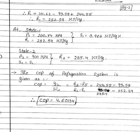
 A Refrigeration System Using R-134A In a refrigeration system, the refrigerant R-134A begins as saturated vapor at -15°(State 1). It then goes through a reversible adiabatic compressor to reach State 2. After flowing through the condenser (a heat exchanger), the refrigerant exits as saturated liquid at 70°C (State 3). It is then throttled by going through an expansion valve, to reach State 4. It finishes the cycle by going through another heat exchanger (the evaporator), to return to State 1....
Condenser Compressor An ideal vapor-compression refrigeration cycle is modified to include a counter-flow heat exchanger as...
 Condenser Compressor An ideal vapor-compression refrigeration cycle is modified to include a counter-flow heat exchanger as shown. Refrigerant 134a leaves the evaporator as saturated vapor at 0.10 MPa and is heated at constant pressure to 20°C before entering the compressor. Following isentropic compression to 1.4 MPa, the refrigerant passes through the condenser and exits at 45°C and 1.4 MPa. The liquid then passes through the heat exchanger and enters the expansion valve at 1.4 MPa. The mass flow rate of...
A two-stage compression refrigeration system with an adiabatic liquid-vapor separation unit uses refrigerant-134a as working fluid....
 A two-stage compression refrigeration system with an adiabatic liquid-vapor separation unit uses refrigerant-134a as working fluid. The system operates the evaporator at 0.4 MPa, the condenser at 1.6 MPa, and the separator at 0.8 MPa. The compressors use 25 kW of power. Given that the refrigerant is saturated liquid at the inlet of each expansion valve and saturated vapor at the inlet of each compressor, and the compressors are isentropic: (0) show the process on a T-s diagram; ) calculate...
2. (10 points) An ideal vapor-compression refrigeration cycle is modified to include a counter- flow heat...
 2. (10 points) An ideal vapor-compression refrigeration cycle is modified to include a counter- flow heat exchanger, as shown below. Ammonia leaves the evaporator as saturated vapor at 1.0 bar and is heated at constant pressure to 5 "C before entering the compressor. Following isentropic compression to 18 bar, the refrigerant passes through the condenser, exiting at 40 C, 18 bar. The liquid then passes through the heat exchanger, entering the expansion valve at 18 bar. If the mass flow...
4. (10 points) An ideal vapor-compression refrigeration cycle is modified to include a counter- f...
 4. (10 points) An ideal vapor-compression refrigeration cycle is modified to include a counter- flow heat exchanger, as shown below.Ammonia leaves the evaporator as saturated vapor at 1.0 bar and is heated at constant pressure to S "C before entering the compressor. Following isentropic compression to 18 bar, the refrigerant passes through the condenser, exiting at 40 18 bar. The liquid then passes through the heat exchanger, entering the expansion valve at 18 bar. If the mass flow rate of...
A two-stage compression refrigeration system with an adiabatic liquid-vapor separation unit uses refrigerant-134a as working fluid....
A two-stage compression refrigeration system with an adiabatic liquid-vapor separation unit uses refrigerant-134a as working fluid. the system operates the evaporator at 0.4Mpa, the condenser at 1.6Mpa and the separator at 0.8 Mpa. The compressors use 25kW of power. Given that the refrigerant is saturated liquid at the inlet of each compressor, and the compressors are isentropic: i) show the process on a T-s diagram, ii) calculate the rate of cooling provided by the evaporator, the COP of the heat...
EXAMPLE 6 A household refrigeration system works with a vapor compression refrigeration system with two evaporators...
 EXAMPLE 6 A household refrigeration system works with a vapor compression refrigeration system with two evaporators using Refrigerant 134a as the working fluid. This arrangement is used to achieve refrigeration at two different temperatures with a single compressor and a single condenser. The low temperature evaporator operates at -18°C with saturated vapor at its exit and has a refrigerating capacity of 10.5 kW (3 tons). The higher- temperature evaporator produces saturated vapor at 3.2 bar at its exit and has...
A two-stage cascade refrigeration system operates between the pressure limits of 1.4MPa and 200 kPa with...
 A two-stage cascade refrigeration system operates between the pressure limits of 1.4MPa and 200 kPa with refrigerant-134a. The fluid leaves the condenser as a saturated liquid and is throttled to a flash chamber operating at 0.50 MPa. Part of the refrigerant evaporates in the flashing process, and this vapor is mixed with the refrigerant leaving the low-pressurin compressor. The liguid in the flash chamber iS throttled to the evaporator pressure and cools the refrigerated space. The mass flow rate of...
5/An ammonia refrigeration system consists of two stages compressors, two cvaporators, flash intereooler and sub-cooler, heat...
 5/An ammonia refrigeration system consists of two stages compressors, two cvaporators, flash intereooler and sub-cooler, heat exchanger and condenser. Ammonia vapor condenses in the condenser at 40 "C. The amount of liquid refrigerant goes to the low temperature evaporator is sub-cooled 10 °C in the liquid sub- cooler and another 10 °C in the liquid-vapor heat exchanger. Vapor leaves the low pressure evaporator saturated at -30 °C, and then it is superheated in the heat exchanger at the same pressure....
A 100-ton refrigeration system operates on the simple vapor compression refrigeration system with R-22 as the...
A 100-ton refrigeration system operates on the simple vapor compression refrigeration system with R-22 as the working fluid. The evaporator pressure is 2 bar and the condenser pressure is 30 bar. The refrigerant leaves the compressor at 160oC. 1 ton of refrigeration = 3.517 kW Determine the cooling load, in kW. Plot all five points (1, 2s, 2a, 3, 4) on the P-h diagram. Determine the power consumed by the refrigeration system, in kW. Determine the COP of the system. Isentropic efficiency...
 A Refrigeration System Using R-134A In a refrigeration system, the refrigerant R-134A begins as saturated vapor at -15°(State 1). It then goes through a reversible adiabatic compressor to reach State 2. After flowing through the condenser (a heat exchanger), the refrigerant exits as saturated liquid at 70°C (State 3). It is then throttled by going through an expansion valve, to reach State 4. It finishes the cycle by going through another heat exchanger (the evaporator), to return to State 1....
 Condenser Compressor An ideal vapor-compression refrigeration cycle is modified to include a counter-flow heat exchanger as shown. Refrigerant 134a leaves the evaporator as saturated vapor at 0.10 MPa and is heated at constant pressure to 20°C before entering the compressor. Following isentropic compression to 1.4 MPa, the refrigerant passes through the condenser and exits at 45°C and 1.4 MPa. The liquid then passes through the heat exchanger and enters the expansion valve at 1.4 MPa. The mass flow rate of...
 A two-stage compression refrigeration system with an adiabatic liquid-vapor separation unit uses refrigerant-134a as working fluid. The system operates the evaporator at 0.4 MPa, the condenser at 1.6 MPa, and the separator at 0.8 MPa. The compressors use 25 kW of power. Given that the refrigerant is saturated liquid at the inlet of each expansion valve and saturated vapor at the inlet of each compressor, and the compressors are isentropic: (0) show the process on a T-s diagram; ) calculate...
 2. (10 points) An ideal vapor-compression refrigeration cycle is modified to include a counter- flow heat exchanger, as shown below. Ammonia leaves the evaporator as saturated vapor at 1.0 bar and is heated at constant pressure to 5 "C before entering the compressor. Following isentropic compression to 18 bar, the refrigerant passes through the condenser, exiting at 40 C, 18 bar. The liquid then passes through the heat exchanger, entering the expansion valve at 18 bar. If the mass flow...
 4. (10 points) An ideal vapor-compression refrigeration cycle is modified to include a counter- flow heat exchanger, as shown below.Ammonia leaves the evaporator as saturated vapor at 1.0 bar and is heated at constant pressure to S "C before entering the compressor. Following isentropic compression to 18 bar, the refrigerant passes through the condenser, exiting at 40 18 bar. The liquid then passes through the heat exchanger, entering the expansion valve at 18 bar. If the mass flow rate of...
 EXAMPLE 6 A household refrigeration system works with a vapor compression refrigeration system with two evaporators using Refrigerant 134a as the working fluid. This arrangement is used to achieve refrigeration at two different temperatures with a single compressor and a single condenser. The low temperature evaporator operates at -18°C with saturated vapor at its exit and has a refrigerating capacity of 10.5 kW (3 tons). The higher- temperature evaporator produces saturated vapor at 3.2 bar at its exit and has...
 A two-stage cascade refrigeration system operates between the pressure limits of 1.4MPa and 200 kPa with refrigerant-134a. The fluid leaves the condenser as a saturated liquid and is throttled to a flash chamber operating at 0.50 MPa. Part of the refrigerant evaporates in the flashing process, and this vapor is mixed with the refrigerant leaving the low-pressurin compressor. The liguid in the flash chamber iS throttled to the evaporator pressure and cools the refrigerated space. The mass flow rate of...
 5/An ammonia refrigeration system consists of two stages compressors, two cvaporators, flash intereooler and sub-cooler, heat exchanger and condenser. Ammonia vapor condenses in the condenser at 40 "C. The amount of liquid refrigerant goes to the low temperature evaporator is sub-cooled 10 °C in the liquid sub- cooler and another 10 °C in the liquid-vapor heat exchanger. Vapor leaves the low pressure evaporator saturated at -30 °C, and then it is superheated in the heat exchanger at the same pressure....
Most questions answered within 3 hours.
-
Please Solve correctly ASAP.
A class consist of 55 students,
20 are juniors, 5 are seniors,...
asked 24 minutes ago -
Part A
In a seven-step synthesis, what is the yield of the target
molecule if each...
asked 6 minutes ago -
The current profit for a subunit is $36,000. Its current
invested capital is $200,000. The subunit...
asked 20 minutes ago -
1. (12-8) Jacqueline’s Sleep store sells water beds and assorted
supplies. Her best selling bed, the...
asked 26 minutes ago -
In the laboratory you dissolve 23.5 g of silver(I) nitrate in a
volumetric flask and add...
asked 24 minutes ago -
7) A random sample of 40 men were asked how if they enjoyed
watching sports more...
asked 39 minutes ago -
Air in a balloon does 32 J of work while absorbing 79 J of heat.
What...
asked 44 minutes ago -
The output torque of a motor is 69.2 lb-ft when it operates at
950 rpm. Calculate...
asked 48 minutes ago -
Calculate the rotational inertia of a wheel that has a kinetic
energy of 40.4 kJ when...
asked 50 minutes ago -
A.) Suppose that investors in the bonds market find that risk
levels decrease. Consequently, the demand...
asked 1 hour ago -
In a class of 120 students, 60 take english, 50 take spanish, 20
take both english...
asked 1 hour ago -
What is one way in which the power of the UN Security Council is
limited? Question...
asked 1 hour ago