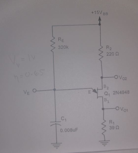
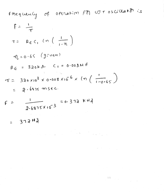
what is the frequency of operation for the UJT relaxation oscillator using the given values
Homework Answers
Add Answer to:
what is the frequency of operation for the UJT relaxation oscillator using the given values +15V...
Solution problems: solve for the unknown quantity. 7. Calculate the frequency of a UJT relaxation oscillator...
 Solution problems: solve for the unknown quantity. 7. Calculate the frequency of a UJT relaxation oscillator when RE is 10K ohms and CE is 0.1uF. [Worth 5 points] 8. Suppose a square wave signal has a 65 percent duty cycle and an on-state voltage of 40 volts DC. What is the average DC voltage? [Worth 5 points] 9. If the full temperature range of an On-Off heating system is from 30 to 100 degrees and the differential gap is 5...
Examine the frequency characteristic of an audio frequency oscillator by varying the component's values, as shown...
 Examine the frequency characteristic of an audio frequency oscillator by varying the component's values, as shown in Fig. 3.1. (1+1) The following data is available. B=1/3, R1=40-49k12, R2=45-52k 2, C1=0.001-0.003 uF, C2=0.002-0.005uF. Figure out the resonance frequency as well based on data variability. (1+1) Explain why this kind of oscillator only operates at resonance frequency. Aid with circuit explanation. (2) Rf Ri vo + 디 RI & R2 Fig. 3.1
I just need help with the theoretical output frequency and amplitude for part (26) using the...
 I just need help with the theoretical output frequency and
amplitude for part (26) using the data from Project D.
Relaxation Oscillator R Vout C R2 ww R1 Figure 6-Relaxation Oscillator Project A С R Rl R2 0.1 uF 15K 18K 3.ЗК 12K В 0.22 uF 4.7K 15K C 0.22 uF 10K 5.6K 15K 15K 0.1 uF 20K 6.8K Table 5- Component Values for Relaxation Oscillator (25) Construct the circuit from Figure 6 with the component values according to Table...
I just need help with the theoretical output frequency and
amplitude for part (26) using the data from Project D.
Relaxation Oscillator R Vout C R2 ww R1 Figure 6-Relaxation Oscillator Project A С R Rl R2 0.1 uF 15K 18K 3.ЗК 12K В 0.22 uF 4.7K 15K C 0.22 uF 10K 5.6K 15K 15K 0.1 uF 20K 6.8K Table 5- Component Values for Relaxation Oscillator (25) Construct the circuit from Figure 6 with the component values according to Table...
Use Exact Analysis Use 4 decimal places, no commas. a. VCC = 15V b. R1 =...
Use Exact Analysis Use 4 decimal places, no commas. a. VCC = 15V b. R1 = 55 kΩ c. R2 = 15 kΩ d. RC = 2.5 kΩ e. RE = 1.5 kΩ f. RS = 15 Ω g. RL = 500 Ω h. βDC = 50 i. βac = 100 Single-stage, voltage-divider biased, common-emitter with **C1 and C2 are coupling capacitors. C3 is bypass capacitor Given: A. VB = [a] V ; B. VE = [b] V ; C....
Given Beta=100. c. What region of operation is the BJT operating in? How do you know?...
 Given Beta=100.
c. What region of operation is the BJT operating in? How do you
know?
Hint: compare the voltages at the Base, Collector, and
Emitter.
d. Calculate theoretical calculations for VB, VC, VE, IB, IC, and
IE
V1 12E R4 470k R1 22k 01 Qbreakn R3 270k R2 16k 0
Given Beta=100.
c. What region of operation is the BJT operating in? How do you
know?
Hint: compare the voltages at the Base, Collector, and
Emitter.
d. Calculate theoretical calculations for VB, VC, VE, IB, IC, and
IE
V1 12E R4 470k R1 22k 01 Qbreakn R3 270k R2 16k 0
4. A single phase inverter shown below is using a 1:10 step up transformer which supplies...
 4. A single phase inverter shown below is using a 1:10 step up transformer which supplies the power to 20W load lamps. If the secondary voltage has rms value of 120Vac and the transformer total winding resistance is 0.8W. Determine the rms input voltage [15 Marks) i. Determine the period and frequency of oscillation for an inverter if the components have the following values: R1=2K, R2=20K, C1=0.04m F & C2=0.05mF [15 Marks) ii. Determine the value of capacitors to be...
Given the Wien Bridge shown below C2 R4 U1 0 R1 D1 R3 D2 R2 Al What is the frequency at which it oscillates if R R 47 k, and C C 4.7 nE? B] what is the loop gain T(jf) at startup if R1 = 23 kQ. R2 =...
 Given the Wien Bridge shown below C2 R4 U1 0 R1 D1 R3 D2 R2 Al What is the frequency at which it oscillates if R R 47 k, and C C 4.7 nE? B] what is the loop gain T(jf) at startup if R1 = 23 kQ. R2 = 10 kQ, R3 = 100 kO? C] What is the loop gain if the diodes are assuming to be heavily conducting? D] What is the purpose in using the two...
Problem 3 For the given measurement system, which measures temperature using an RTD, of type PT100,...
 Problem 3 For the given measurement system, which measures temperature using an RTD, of type PT100, that is 100 Ohms at 0 C. If R2-R3 1000 Ohms, R1 110, At what temperature the bridge will be balanced, knowing that RTD is approximated with the given 1. equation Rold(1+0.004(change in temperature)) Rew= 2. If the amplifier has a gain of 10; determine accepted RA values of Rf and Rin RS N If the output of the amplifire is limited from -2.5...
PROBLEM STATEMENT The mini-calculator will use a small ALU to perform arithmetic operations on two 4-bit values which are set using switches. The ALU operations described below are implemented with a...
 PROBLEM STATEMENT The mini-calculator will use a small ALU to perform arithmetic operations on two 4-bit values which are set using switches. The ALU operations described below are implemented with an Adder/Subtractor component. A pushbutton input allows the current arithmetic result to be saved. An upgraded mini-calculator allows the saved value to be used in place of B as one of the operands. The small ALU that you will design will use the 4-bit adder myadder4 to do several possible...
ans, RA = 721.5 kohms, RB = 360.8 kohms, R3 = 3.5kohms as an example solution. Question 7 (6 marks) You have been given...
 ans,
RA = 721.5 kohms, RB = 360.8 kohms, R3 = 3.5kohms as an example
solution.
Question 7 (6 marks) You have been given a 555 Timer, an LED with Von 2V, a 9V battery that can comfortably supply 5mA of current without loss of voltage, a 1 μF capacitor and access to any resistor values you want. You are to design a circuit that causes the LED to flash periodically once per second with a duty cycle of 75%....
ans,
RA = 721.5 kohms, RB = 360.8 kohms, R3 = 3.5kohms as an example
solution.
Question 7 (6 marks) You have been given a 555 Timer, an LED with Von 2V, a 9V battery that can comfortably supply 5mA of current without loss of voltage, a 1 μF capacitor and access to any resistor values you want. You are to design a circuit that causes the LED to flash periodically once per second with a duty cycle of 75%....
 Solution problems: solve for the unknown quantity. 7. Calculate the frequency of a UJT relaxation oscillator when RE is 10K ohms and CE is 0.1uF. [Worth 5 points] 8. Suppose a square wave signal has a 65 percent duty cycle and an on-state voltage of 40 volts DC. What is the average DC voltage? [Worth 5 points] 9. If the full temperature range of an On-Off heating system is from 30 to 100 degrees and the differential gap is 5...
 Examine the frequency characteristic of an audio frequency oscillator by varying the component's values, as shown in Fig. 3.1. (1+1) The following data is available. B=1/3, R1=40-49k12, R2=45-52k 2, C1=0.001-0.003 uF, C2=0.002-0.005uF. Figure out the resonance frequency as well based on data variability. (1+1) Explain why this kind of oscillator only operates at resonance frequency. Aid with circuit explanation. (2) Rf Ri vo + 디 RI & R2 Fig. 3.1
 I just need help with the theoretical output frequency and
amplitude for part (26) using the data from Project D.
Relaxation Oscillator R Vout C R2 ww R1 Figure 6-Relaxation Oscillator Project A С R Rl R2 0.1 uF 15K 18K 3.ЗК 12K В 0.22 uF 4.7K 15K C 0.22 uF 10K 5.6K 15K 15K 0.1 uF 20K 6.8K Table 5- Component Values for Relaxation Oscillator (25) Construct the circuit from Figure 6 with the component values according to Table...
I just need help with the theoretical output frequency and
amplitude for part (26) using the data from Project D.
Relaxation Oscillator R Vout C R2 ww R1 Figure 6-Relaxation Oscillator Project A С R Rl R2 0.1 uF 15K 18K 3.ЗК 12K В 0.22 uF 4.7K 15K C 0.22 uF 10K 5.6K 15K 15K 0.1 uF 20K 6.8K Table 5- Component Values for Relaxation Oscillator (25) Construct the circuit from Figure 6 with the component values according to Table...
 Given Beta=100.
c. What region of operation is the BJT operating in? How do you
know?
Hint: compare the voltages at the Base, Collector, and
Emitter.
d. Calculate theoretical calculations for VB, VC, VE, IB, IC, and
IE
V1 12E R4 470k R1 22k 01 Qbreakn R3 270k R2 16k 0
Given Beta=100.
c. What region of operation is the BJT operating in? How do you
know?
Hint: compare the voltages at the Base, Collector, and
Emitter.
d. Calculate theoretical calculations for VB, VC, VE, IB, IC, and
IE
V1 12E R4 470k R1 22k 01 Qbreakn R3 270k R2 16k 0
 4. A single phase inverter shown below is using a 1:10 step up transformer which supplies the power to 20W load lamps. If the secondary voltage has rms value of 120Vac and the transformer total winding resistance is 0.8W. Determine the rms input voltage [15 Marks) i. Determine the period and frequency of oscillation for an inverter if the components have the following values: R1=2K, R2=20K, C1=0.04m F & C2=0.05mF [15 Marks) ii. Determine the value of capacitors to be...
 Given the Wien Bridge shown below C2 R4 U1 0 R1 D1 R3 D2 R2 Al What is the frequency at which it oscillates if R R 47 k, and C C 4.7 nE? B] what is the loop gain T(jf) at startup if R1 = 23 kQ. R2 = 10 kQ, R3 = 100 kO? C] What is the loop gain if the diodes are assuming to be heavily conducting? D] What is the purpose in using the two...
 Problem 3 For the given measurement system, which measures temperature using an RTD, of type PT100, that is 100 Ohms at 0 C. If R2-R3 1000 Ohms, R1 110, At what temperature the bridge will be balanced, knowing that RTD is approximated with the given 1. equation Rold(1+0.004(change in temperature)) Rew= 2. If the amplifier has a gain of 10; determine accepted RA values of Rf and Rin RS N If the output of the amplifire is limited from -2.5...
 PROBLEM STATEMENT The mini-calculator will use a small ALU to perform arithmetic operations on two 4-bit values which are set using switches. The ALU operations described below are implemented with an Adder/Subtractor component. A pushbutton input allows the current arithmetic result to be saved. An upgraded mini-calculator allows the saved value to be used in place of B as one of the operands. The small ALU that you will design will use the 4-bit adder myadder4 to do several possible...
 ans,
RA = 721.5 kohms, RB = 360.8 kohms, R3 = 3.5kohms as an example
solution.
Question 7 (6 marks) You have been given a 555 Timer, an LED with Von 2V, a 9V battery that can comfortably supply 5mA of current without loss of voltage, a 1 μF capacitor and access to any resistor values you want. You are to design a circuit that causes the LED to flash periodically once per second with a duty cycle of 75%....
ans,
RA = 721.5 kohms, RB = 360.8 kohms, R3 = 3.5kohms as an example
solution.
Question 7 (6 marks) You have been given a 555 Timer, an LED with Von 2V, a 9V battery that can comfortably supply 5mA of current without loss of voltage, a 1 μF capacitor and access to any resistor values you want. You are to design a circuit that causes the LED to flash periodically once per second with a duty cycle of 75%....
Most questions answered within 3 hours.
-
The extent to which assets are financed by borrowed funds and
other liabilities is indicated by:...
asked 29 minutes ago -
Explain in detail
Germany is the fifth largest economy
explain what goods and services Germany specializes...
asked 44 minutes ago -
The density of platinum is 21.45 g/mL. If a cube of platinum
with a mass of...
asked 49 minutes ago -
Accounts Receivable
Sales
A/R Posting
Extended Sales Invoice
Packing Slip
Compare invoice to packing slip 2...
asked 52 minutes ago -
Michaella, age 23, is a full-time law student and is claimed by
her parents as a...
asked 53 minutes ago -
Why are polymers not typically casted into products?
asked 1 hour ago -
When rolling a die 129 times, what is the probability of rolling
a 6 no more...
asked 1 hour ago -
4. A call option currently sells for $7.75. It has a strike
price of $85 and...
asked 1 hour ago -
1.
You need to prepare 10.0 liters of an acid aqueous solution with a
pH of...
asked 1 hour ago -
Along an aggregate supply curve, if the level of output is less
than the natural level...
asked 1 hour ago -
By 2025, annual consumption in emerging markets will total $30
trillion and contribute more than ________...
asked 1 hour ago -
At what point does reformation cease to be a viable option for
those who are oppressed...
asked 1 hour ago