
Homework Answers


Thanks
Add Answer to:
Problem 3 For the given measurement system, which measures temperature using an RTD, of type PT100,...
op amp LM358N is used. This device is actually temperature measurement. Instead of resistor of 174Ohms, it should be a...
 op amp LM358N is used. This device is actually temperature
measurement. Instead of resistor of 174Ohms, it should be a RTD or
PT100, but I don't have in the lab right now, so this is
simulation. With this resistance, temperature should be around
188-189 Celsius. I hope this part is clear. In the lab, for
different temperatures I will put different resistor, 190 Ohms, 280
Ohms etc. Output of the amplifiers should be connected to pins A0
and A1 on...
op amp LM358N is used. This device is actually temperature
measurement. Instead of resistor of 174Ohms, it should be a RTD or
PT100, but I don't have in the lab right now, so this is
simulation. With this resistance, temperature should be around
188-189 Celsius. I hope this part is clear. In the lab, for
different temperatures I will put different resistor, 190 Ohms, 280
Ohms etc. Output of the amplifiers should be connected to pins A0
and A1 on...
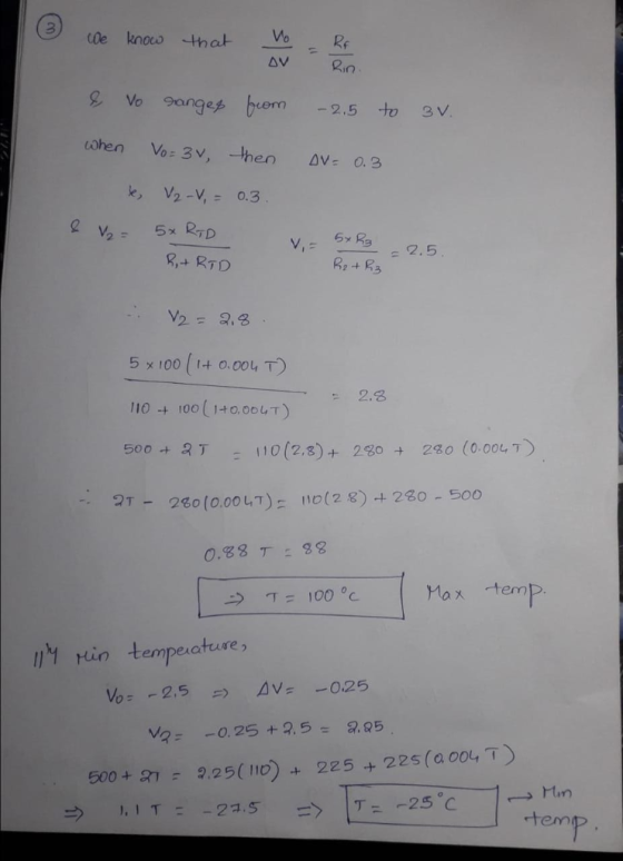
Problem 3 (30 pts.) A J-type thermocouple is calibrated against an RTD standard within 20.02°C between...
 Problem 3 (30 pts.) A J-type thermocouple is calibrated against an RTD standard within 20.02°C between 0º and 200°C. The emf is measured with a potentiometer having 0.005 mV resolution and an uncertainty of 0.045 mV over its operating range. The reference junction temperature is provided by an ice bath. The calibration procedure yields the following equation: T(°C) = 0.11 + 19.16V - 0.06V2, where the units of voltage V is mV. This second order curve fit has an error...
QUESTION 3 Given the following circuit for an INA121 instrumental amplifier. What is Vout in terms...
 QUESTION 3 Given the following circuit for an INA121 instrumental amplifier. What is Vout in terms of V1 and V2? RG_01 FI Vout REF RG AD8421 5V o A. Vous = 10(V2-V1) o B. Vout =(V2-V1) o C. Vour = 3(V2-V1) O D. Vour = 2(V2 - 12) QUESTION 4 Which value of Rc for the INA121 instrumental amplifier would you have the best measurement for Rsense in the following circuit. 5V Rlimit RG01 Rsense RG Vsense REF RGAD8421 1N4148...
SOLVE ALL THE 3 questions using the properties of OPERATIONAL AMPLIFIER AND BJTs. Problem 1 10...
 SOLVE ALL THE 3 questions using the properties of
OPERATIONAL AMPLIFIER AND BJTs.
Problem 1 10 Marks A humidity sensor produces linear output voltage in the range of 0 V to 10 mV for humidity levels of 0 % to 100 % respectively. You are required to design the inverting op-amp circuit to achieve the voltage gain of 1000. Op-amp feed-back current should be 0.2 mA when op-amp output is at maximum. Solution: Problem 2 We discussed the summing circuit...
SOLVE ALL THE 3 questions using the properties of
OPERATIONAL AMPLIFIER AND BJTs.
Problem 1 10 Marks A humidity sensor produces linear output voltage in the range of 0 V to 10 mV for humidity levels of 0 % to 100 % respectively. You are required to design the inverting op-amp circuit to achieve the voltage gain of 1000. Op-amp feed-back current should be 0.2 mA when op-amp output is at maximum. Solution: Problem 2 We discussed the summing circuit...
Problem 3: Design Problem On Figure P3a, you have a Common Source (CS) n-channel MOSFET amplifier....
 Problem 3: Design Problem On Figure P3a, you have a Common Source (CS) n-channel MOSFET amplifier. Notice the absence of a source resistor Rsig and load resistor R. If we know how the present amplifier (the one on Figure P3a) behaves without Rsig and RL, we can infer its behaviors if Rsig and R were to be added. design the amplifier circuit on Figure P3a, i.e., you have to find appropriate values for RGj You are to RG,, RD, and...
summatize the following info and break them into differeng key points. write them in yojr own...
 summatize the following info and break them into differeng key points. write them in yojr own words
apartus
6.1 Introduction—The design of a successful hot box appa- ratus is influenced by many factors. Before beginning the design of an apparatus meeting this standard, the designer shall review the discussion on the limitations and accuracy, Section 13, discussions of the energy flows in a hot box, Annex A2, the metering box wall loss flow, Annex A3, and flanking loss, Annex...
summatize the following info and break them into differeng key points. write them in yojr own words
apartus
6.1 Introduction—The design of a successful hot box appa- ratus is influenced by many factors. Before beginning the design of an apparatus meeting this standard, the designer shall review the discussion on the limitations and accuracy, Section 13, discussions of the energy flows in a hot box, Annex A2, the metering box wall loss flow, Annex A3, and flanking loss, Annex...
summarizr the followung info and write them in your own words and break them into different...
summarizr the followung info and write them in your own words and break them into different key points. 6.5 Metering Chamber: 6.5.1 The minimum size of the metering box is governed by the metering area required to obtain a representative test area for the specimen (see 7.2) and for maintenance of reasonable test accuracy. For example, for specimens incorporating air spaces or stud spaces, the metering area shall span an integral number of spaces (see 5.5). The depth of...
 op amp LM358N is used. This device is actually temperature
measurement. Instead of resistor of 174Ohms, it should be a RTD or
PT100, but I don't have in the lab right now, so this is
simulation. With this resistance, temperature should be around
188-189 Celsius. I hope this part is clear. In the lab, for
different temperatures I will put different resistor, 190 Ohms, 280
Ohms etc. Output of the amplifiers should be connected to pins A0
and A1 on...
op amp LM358N is used. This device is actually temperature
measurement. Instead of resistor of 174Ohms, it should be a RTD or
PT100, but I don't have in the lab right now, so this is
simulation. With this resistance, temperature should be around
188-189 Celsius. I hope this part is clear. In the lab, for
different temperatures I will put different resistor, 190 Ohms, 280
Ohms etc. Output of the amplifiers should be connected to pins A0
and A1 on...
 Problem 3 (30 pts.) A J-type thermocouple is calibrated against an RTD standard within 20.02°C between 0º and 200°C. The emf is measured with a potentiometer having 0.005 mV resolution and an uncertainty of 0.045 mV over its operating range. The reference junction temperature is provided by an ice bath. The calibration procedure yields the following equation: T(°C) = 0.11 + 19.16V - 0.06V2, where the units of voltage V is mV. This second order curve fit has an error...
 QUESTION 3 Given the following circuit for an INA121 instrumental amplifier. What is Vout in terms of V1 and V2? RG_01 FI Vout REF RG AD8421 5V o A. Vous = 10(V2-V1) o B. Vout =(V2-V1) o C. Vour = 3(V2-V1) O D. Vour = 2(V2 - 12) QUESTION 4 Which value of Rc for the INA121 instrumental amplifier would you have the best measurement for Rsense in the following circuit. 5V Rlimit RG01 Rsense RG Vsense REF RGAD8421 1N4148...
 SOLVE ALL THE 3 questions using the properties of
OPERATIONAL AMPLIFIER AND BJTs.
Problem 1 10 Marks A humidity sensor produces linear output voltage in the range of 0 V to 10 mV for humidity levels of 0 % to 100 % respectively. You are required to design the inverting op-amp circuit to achieve the voltage gain of 1000. Op-amp feed-back current should be 0.2 mA when op-amp output is at maximum. Solution: Problem 2 We discussed the summing circuit...
SOLVE ALL THE 3 questions using the properties of
OPERATIONAL AMPLIFIER AND BJTs.
Problem 1 10 Marks A humidity sensor produces linear output voltage in the range of 0 V to 10 mV for humidity levels of 0 % to 100 % respectively. You are required to design the inverting op-amp circuit to achieve the voltage gain of 1000. Op-amp feed-back current should be 0.2 mA when op-amp output is at maximum. Solution: Problem 2 We discussed the summing circuit...
 Problem 3: Design Problem On Figure P3a, you have a Common Source (CS) n-channel MOSFET amplifier. Notice the absence of a source resistor Rsig and load resistor R. If we know how the present amplifier (the one on Figure P3a) behaves without Rsig and RL, we can infer its behaviors if Rsig and R were to be added. design the amplifier circuit on Figure P3a, i.e., you have to find appropriate values for RGj You are to RG,, RD, and...
 summatize the following info and break them into differeng key points. write them in yojr own words
apartus
6.1 Introduction—The design of a successful hot box appa- ratus is influenced by many factors. Before beginning the design of an apparatus meeting this standard, the designer shall review the discussion on the limitations and accuracy, Section 13, discussions of the energy flows in a hot box, Annex A2, the metering box wall loss flow, Annex A3, and flanking loss, Annex...
summatize the following info and break them into differeng key points. write them in yojr own words
apartus
6.1 Introduction—The design of a successful hot box appa- ratus is influenced by many factors. Before beginning the design of an apparatus meeting this standard, the designer shall review the discussion on the limitations and accuracy, Section 13, discussions of the energy flows in a hot box, Annex A2, the metering box wall loss flow, Annex A3, and flanking loss, Annex...
Most questions answered within 3 hours.
-
1. Which of the following is NOT an argument that McMahan uses
to show that jus...
asked 16 minutes ago -
A crate slides up a frictionless slope. At the end of 3 seconds
its velocity is...
asked 33 minutes ago -
Use the following information to answer the next seven
questions.
Suppose there are three potential states...
asked 29 minutes ago -
If we only have interstitial and substitutional diffusion, then
what do we consider the process of...
asked 45 minutes ago -
You look at yourself in a shiny 9.6-cm-diameter Christmas tree
ball.
If your face is 21.0...
asked 47 minutes ago -
If we were to measure the relaxation time of a muscle after
undergoing tetanus compared to...
asked 46 minutes ago -
4CO(g) + 8H2(g) -----> 3CH4(g) +
CO2(g) + 2H2O(l)
Use the following data as needed to...
asked 49 minutes ago -
without using map
1. Write a C++ program to find out the top 10 words in...
asked 1 hour ago -
1)Calculate the percent ionization of a
0.330 M solution of hypochlorous
acid.
% Ionization = %...
asked 1 hour ago -
1a) How many grams of K2SO4 are in 250mL
of 0.11 M K2SO4 solution?
_____ g...
asked 56 minutes ago -
The vapor pressure of a solution containing 38.7 g glycerin
(C3H8O3) in 146.2 g ethanol (C2H5OH)...
asked 1 hour ago -
A physics major is cooking breakfast when he notices that the
frictional force between the steel...
asked 1 hour ago