
Homework Answers


Add Answer to:
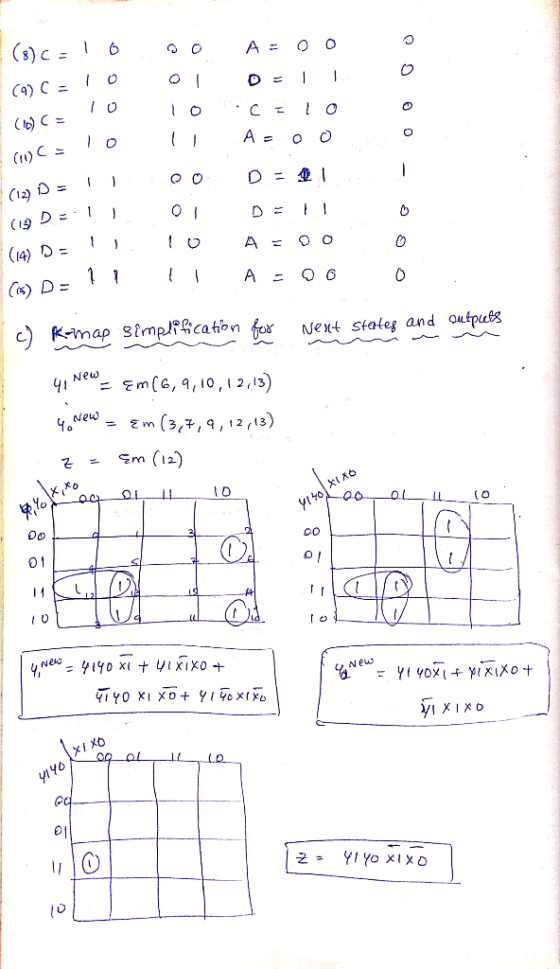
P6 (15 points): The FSM state diagram below has two inputs x1 and xo In addition,...
1. Given the state diagram shown below for a state machine with one-bit input W and two-bit outpu...
 1. Given the state diagram shown below for a state machine with
one-bit input W and two-bit output Z:
a. (20 points) Using the state assignments below, make the
state-assigned table. Let S0 = 001, S1 = 010, and S2 = 100.
b. (20 points) Let the state variables be Y2, Y1, and Y0. Derive
an expression for each of the next state variables.
c. (10 points) Derive expressions for the output of this state
diagram.
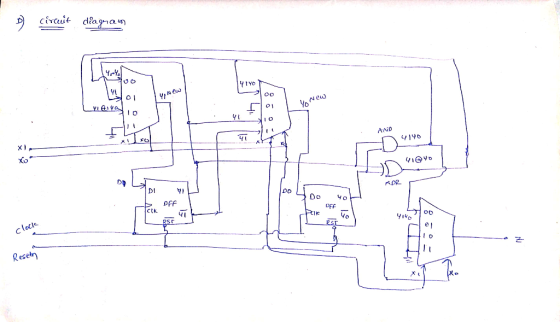
d. (20 points) Draw...
1. Given the state diagram shown below for a state machine with
one-bit input W and two-bit output Z:
a. (20 points) Using the state assignments below, make the
state-assigned table. Let S0 = 001, S1 = 010, and S2 = 100.
b. (20 points) Let the state variables be Y2, Y1, and Y0. Derive
an expression for each of the next state variables.
c. (10 points) Derive expressions for the output of this state
diagram.
d. (20 points) Draw...
Design and Draw the Circuit Schematic for the FSM if it were a Mealy Machine. Your...
 Design and Draw the Circuit Schematic for the FSM if it were a Mealy Machine. Your answer must show all the below items in the order. Combined State transition table and Output Table Combined State transition table and Output Table with encodings Boolean expressions for Next State Logic Boolean expressions for Output Logic FSM Circuit Schematic with Inputs, Next State Logic, State Register, Output logic and Outputs The FSM State transition diagram for Mealy Machine is 1/1 Reset 1/0 1/0...
Given the FSM schematic below, answer the following question Question 1. (30 POINTS) Given the FSM schematic below, answer the following questions: A, A CLK si s, Output 0 0 Reset 1.A.) (6 POINTS)...
 Given the FSM schematic below, answer the following
question
Question 1. (30 POINTS) Given the FSM schematic below, answer the following questions: A, A CLK si s, Output 0 0 Reset 1.A.) (6 POINTS) What are the Boolean equations for next state and output logic? 1.B.) (4 POINTS) Is this a Moore or Mealy FSM? Why? Please explain. 1.C.) (10 POINTS) Draw the truth table for next state and output logic for this circuit. 1.D.) (10 POINTS) Draw the state...
Given the FSM schematic below, answer the following
question
Question 1. (30 POINTS) Given the FSM schematic below, answer the following questions: A, A CLK si s, Output 0 0 Reset 1.A.) (6 POINTS) What are the Boolean equations for next state and output logic? 1.B.) (4 POINTS) Is this a Moore or Mealy FSM? Why? Please explain. 1.C.) (10 POINTS) Draw the truth table for next state and output logic for this circuit. 1.D.) (10 POINTS) Draw the state...
Design the following finite state machine (FSM). It has two 1-bit inputs (in1 and in2) and...
Design the following finite state machine (FSM). It has two 1-bit inputs (in1 and in2) and two 1-bit outputs (out1 and out2). The first output (out1) bit should be equal to one if, on both of the last two cycles, in1 and in2 were EQUAL to each other; otherwise, out1 should equal zero. The second output (out2) should be equal to 1 if, on the last cycle, in1 and in2 were NOT EQUAL to each other; otherwise, out2 should equal...
Finite state machine (FSM) counter design: Gray codes have a useful property in that consecutive numbers differ in only a single bit position. Table 1 lists a 3-bit modulo 8 Gray code representing the...
 Finite state machine (FSM) counter design: Gray
codes have a useful property in that consecutive numbers differ in
only a single bit position. Table 1 lists a 3-bit modulo 8 Gray
code representing the numbers 0 to 7. Design a 3-bit modulo 8 Gray
code counter FSM.
a) First design and sketch a 3-bit modulo 8 Gray code counter
FSM with no inputs and three outputs, the 3-bit signal
Q2:0. (A modulo N counter counts from 0 to N −...
Finite state machine (FSM) counter design: Gray
codes have a useful property in that consecutive numbers differ in
only a single bit position. Table 1 lists a 3-bit modulo 8 Gray
code representing the numbers 0 to 7. Design a 3-bit modulo 8 Gray
code counter FSM.
a) First design and sketch a 3-bit modulo 8 Gray code counter
FSM with no inputs and three outputs, the 3-bit signal
Q2:0. (A modulo N counter counts from 0 to N −...
P5 (20 points): The following Moore FSM state table is incomplete. The clock for this FSM...
 P5 (20 points): The following Moore FSM state table is incomplete. The clock for this FSM (FSM 1) has a period of 100 microseconds such that the button for the input X, controlled by the user, cannot be pressed for only one clock cycle. In addition, button X, when pressed, will output X=0. Current Next State Output State X=0 X=1 w A reset) o IB A B 0 D G I: Draw a state diagram for this state table. II:...
Thats the whole question and its independent from all others. Theres nithing more i could add.
 Thats the whole question and its independent from all others.
Theres nithing more i could add.
3. We want to develop a circuit with one-bit input W and three-bit output Z. The operation of this circuit is as follows: Z is a 3-bit number in modulo 6; that is, Z can only be an integer from 0 to 5. If W-0, then the output z will be decremented by 1 (modulo 6), but if w-1, then the output Z will...
Thats the whole question and its independent from all others.
Theres nithing more i could add.
3. We want to develop a circuit with one-bit input W and three-bit output Z. The operation of this circuit is as follows: Z is a 3-bit number in modulo 6; that is, Z can only be an integer from 0 to 5. If W-0, then the output z will be decremented by 1 (modulo 6), but if w-1, then the output Z will...
Hi Please show steps with clean handwriting. 2) (10 points) A moore FSM has a single infinitely long binary string r as input and a single output. The output is a logic 1 if there are two consecutiv...
Hi Please show steps with clean handwriting. 2) (10 points) A moore FSM has a single infinitely long binary string r as input and a single output. The output is a logic 1 if there are two consecutive 1s or two consecutive 0s received. For example, input = 0 1 1 0 0 0 1 output = 0 0 1 0 1 1 0 Design the FSM. Use full encoding. Construct a timing diagram for the input sequence shown above....
Design a Mealy FSM which functions as a sequence detector, generating two outputs y, z in...
Design a Mealy FSM which functions as a sequence detector, generating two outputs y, z in the following way: a) The signal is applied sequentially to a single input line x. b) Initially both outputs y, z are set to 0. c) Output y is set to 1 when the sequence "10" has been applied to the input x; it should then be reset to 0 and the circuit should continue detecting next occurrence of "10". d) Output z is...
Design a Mealy FSM that will model an elevator that can be at any of 4...
Design a Mealy FSM that will model an elevator that can be at any of 4 floors of EPIC (Ground, First, Second, and Third). There are 2 input buttons that are active High – U to move UP and D to move DOWN. The input buttons are mutually exclusive, that is, only one of them can be active at any point in time (U = 0 and D = 1 makes it go DOWN, and U = 1 and D...
 1. Given the state diagram shown below for a state machine with
one-bit input W and two-bit output Z:
a. (20 points) Using the state assignments below, make the
state-assigned table. Let S0 = 001, S1 = 010, and S2 = 100.
b. (20 points) Let the state variables be Y2, Y1, and Y0. Derive
an expression for each of the next state variables.
c. (10 points) Derive expressions for the output of this state
diagram.
d. (20 points) Draw...
1. Given the state diagram shown below for a state machine with
one-bit input W and two-bit output Z:
a. (20 points) Using the state assignments below, make the
state-assigned table. Let S0 = 001, S1 = 010, and S2 = 100.
b. (20 points) Let the state variables be Y2, Y1, and Y0. Derive
an expression for each of the next state variables.
c. (10 points) Derive expressions for the output of this state
diagram.
d. (20 points) Draw...
 Design and Draw the Circuit Schematic for the FSM if it were a Mealy Machine. Your answer must show all the below items in the order. Combined State transition table and Output Table Combined State transition table and Output Table with encodings Boolean expressions for Next State Logic Boolean expressions for Output Logic FSM Circuit Schematic with Inputs, Next State Logic, State Register, Output logic and Outputs The FSM State transition diagram for Mealy Machine is 1/1 Reset 1/0 1/0...
 Given the FSM schematic below, answer the following
question
Question 1. (30 POINTS) Given the FSM schematic below, answer the following questions: A, A CLK si s, Output 0 0 Reset 1.A.) (6 POINTS) What are the Boolean equations for next state and output logic? 1.B.) (4 POINTS) Is this a Moore or Mealy FSM? Why? Please explain. 1.C.) (10 POINTS) Draw the truth table for next state and output logic for this circuit. 1.D.) (10 POINTS) Draw the state...
Given the FSM schematic below, answer the following
question
Question 1. (30 POINTS) Given the FSM schematic below, answer the following questions: A, A CLK si s, Output 0 0 Reset 1.A.) (6 POINTS) What are the Boolean equations for next state and output logic? 1.B.) (4 POINTS) Is this a Moore or Mealy FSM? Why? Please explain. 1.C.) (10 POINTS) Draw the truth table for next state and output logic for this circuit. 1.D.) (10 POINTS) Draw the state...
 Finite state machine (FSM) counter design: Gray
codes have a useful property in that consecutive numbers differ in
only a single bit position. Table 1 lists a 3-bit modulo 8 Gray
code representing the numbers 0 to 7. Design a 3-bit modulo 8 Gray
code counter FSM.
a) First design and sketch a 3-bit modulo 8 Gray code counter
FSM with no inputs and three outputs, the 3-bit signal
Q2:0. (A modulo N counter counts from 0 to N −...
Finite state machine (FSM) counter design: Gray
codes have a useful property in that consecutive numbers differ in
only a single bit position. Table 1 lists a 3-bit modulo 8 Gray
code representing the numbers 0 to 7. Design a 3-bit modulo 8 Gray
code counter FSM.
a) First design and sketch a 3-bit modulo 8 Gray code counter
FSM with no inputs and three outputs, the 3-bit signal
Q2:0. (A modulo N counter counts from 0 to N −...
 P5 (20 points): The following Moore FSM state table is incomplete. The clock for this FSM (FSM 1) has a period of 100 microseconds such that the button for the input X, controlled by the user, cannot be pressed for only one clock cycle. In addition, button X, when pressed, will output X=0. Current Next State Output State X=0 X=1 w A reset) o IB A B 0 D G I: Draw a state diagram for this state table. II:...
 Thats the whole question and its independent from all others.
Theres nithing more i could add.
3. We want to develop a circuit with one-bit input W and three-bit output Z. The operation of this circuit is as follows: Z is a 3-bit number in modulo 6; that is, Z can only be an integer from 0 to 5. If W-0, then the output z will be decremented by 1 (modulo 6), but if w-1, then the output Z will...
Thats the whole question and its independent from all others.
Theres nithing more i could add.
3. We want to develop a circuit with one-bit input W and three-bit output Z. The operation of this circuit is as follows: Z is a 3-bit number in modulo 6; that is, Z can only be an integer from 0 to 5. If W-0, then the output z will be decremented by 1 (modulo 6), but if w-1, then the output Z will...
Most questions answered within 3 hours.
-
You and your opponent both roll a fair die. If you both roll the
same number,...
asked 8 minutes ago -
In a study of the accuracy of fast food drive-through orders,
Restaurant A had 257 accurate...
asked 8 minutes ago -
Identify and describe in detail the four categories of
institutions that could be included in a...
asked 14 minutes ago -
In python
class Customer:
def __init__(self, customer_id, last_name, first_name, phone_number, address):
self._customer_id = int(customer_id)
self._last_name =...
asked 21 minutes ago -
What is an example of a limitation in implementing a new
ERP system and how it...
asked 16 minutes ago -
In a section of 9.7cm of an artery with a radius of 2.6mm there
is a...
asked 17 minutes ago -
the two carboxylic acid groups of aspartic acid have different
acidities with pKa values of 2.1...
asked 21 minutes ago -
Would CuCO3 aqueous salt combined with calcium chloride
form a solid precipitate? If so, what would...
asked 20 minutes ago -
How do ECM Solutions assist in embedding a culture of continuous
improvement in an organization? (Project...
asked 41 minutes ago -
Directions
These directions introduce the idea of Essential Questions.
Since this may be a new concept...
asked 43 minutes ago -
1.b. Fiscal policy is said to suffer from ‘crowding out’.
Explain what this means and why...
asked 1 hour ago -
The equation for the reaction of nitrogen and oxygen to form
nitrogen oxide is written as...
asked 1 hour ago