
Homework Answers
Add Answer to:
Constants Part A The Wheatstone bridge in the circuit is balanced when If the galvanometer has...
Part B. Wheatstone Bridge Circuit with a Current Source Is R5 R1 R2 Is RL R3 R4 For the circuit a...
 Part B. Wheatstone Bridge Circuit with a Current Source Is R5 R1 R2 Is RL R3 R4 For the circuit as shown below, given that R1-20 Ω,R2= 12 Ω, R3-18 Ω, R4= 20 Ω, R5= 9 Ω , R.-3 ΩΊ,-15 A. I. Wheatstone Bridge Circuit Analysis (a) Determining the load voltage VL-Vab for the Wheatstone bridge circuit with LTspice. Subrnit Answer Tries 0/3 (b) Determining the load current I following from a to b for the Wheatstone bridge circuit with...
Mini-Prj 2. Extraction of Thevenin and Norton Equivalent Circuits by LTspice Part A. Wheatstone B...
 Mini-Prj 2. Extraction of Thevenin and Norton Equivalent Circuits by LTspice Part A. Wheatstone Bridge Circuit with a Voltage Source Vs R5 R1 R2 Vs RL R3 R4 For the circuit as shown below, given that R1= 9 Ω, R2= 17 Ω, R3= 9 Ω' R,-18 Ω, R5= 19 Ω , RL= 2 Ω ,V,-74 V I. Wheatstone Bridge Circuit Analysis (a) Determining the load voltage Vi-Vab for the Wheatstone bridge circuit with LTspice Submit Answer Tries 0/3 (b) Determining...
8. Fig. 1 is a Wheatstone bridge circuit. No current flows through the galvanometer. You find Rx is d. 144 Ω b. 5Ω 1 296-02 12 6.0043 60 Voltage V 8. Fig. 1 is a Wheatstone bridge circuit. No...
 8. Fig. 1 is a Wheatstone bridge circuit. No current flows through the galvanometer. You find Rx is d. 144 Ω b. 5Ω 1 296-02 12 6.0043 60 Voltage V
8. Fig. 1 is a Wheatstone bridge circuit. No current flows through the galvanometer. You find Rx is d. 144 Ω b. 5Ω 1 296-02 12 6.0043 60 Voltage V
8. Fig. 1 is a Wheatstone bridge circuit. No current flows through the galvanometer. You find Rx is d. 144 Ω b. 5Ω 1 296-02 12 6.0043 60 Voltage V
7.- The Wheatstone Bridge. The circuit shown in the figure, called a Wheatstone bridge, is used...
 7.- The Wheatstone Bridge. The circuit shown in the figure, called a Wheatstone bridge, is used to determine the value of an unknown resistor \(X\) by comparison with three resistors \(M, N\), and \(P\) whose resistances can be varied. For each setting, the resistance of each resistor is precisely known. With switches \(K_{1}\) and \(K_{2}\) closed, these resistors are varied until the current in the galvanometer \(G\) is zero; the bridge is then said to be balanced. (a) Show that...
Mini-Prj 2. Extraction of Thevenin and Norton Equivalent Circuits by LTspice Part A. Wheatstone B...
 Mini-Prj 2. Extraction of Thevenin and Norton Equivalent Circuits by LTspice Part A. Wheatstone Bridge Circuit with a Voltage Source Vs R5 R1 R2 Vs RL R3 R4 For the circuit as shown below, given that R1= 9 Ω, R2= 17 Ω, R3= 9 Ω' R,-18 Ω, R5= 19 Ω , RL= 2 Ω ,V,-74 V I. Wheatstone Bridge Circuit Analysis (a) Determining the load voltage Vi-Vab for the Wheatstone bridge circuit with LTspice Submit Answer Tries 0/3 (b) Determining...
Part A. Wheatstone Bridge Circuit with a Voltage Source Vs R5 R1 R2 Vs RL R3 R4 For the circuit a...
 Part A. Wheatstone Bridge Circuit with a Voltage Source Vs R5 R1 R2 Vs RL R3 R4 For the circuit as shown below, given that R1: 23 Ω, R2° 13 O, R,-230, R4% 3 Ω. RS: 28 Ω , RL: 13 Ω ,Vs-90 . I. Wheatstone Bridge Circuit Analysis (a) Determining the load voltage VL-Vab for the Wheatstone bridge circuit with LTspice 1 Submit Answer Tries 0/3 (b) Determining the load current I following from a to b for the...
Mini-Prj 2. Extraction of Thevenin and Norton Equivalent Circuits by LTspice Part B. Wheatstone B...
 Mini-Prj 2. Extraction of Thevenin and Norton Equivalent Circuits by LTspice Part B. Wheatstone Bridge Circuit with a Current Source Is R5 R1 R2 Is RL R3 R4 For the circuit as shown below, given that R1-22 Ω, R2-15 Ω, R3-28 Ω, R4-9 Ω, R5-29 Ω , R.-16 Ω, 1,-6 A. I. Wheatstone Bridge Circuit Analysis (a) Determining the load voltage VL-Vab for the Wheatstone bridge circuit with LTspice. Submit Answer Tries 0/4 (b) Determining the load current IL following...
This circuit is a Wheatstone Bridge. It is used for numerous scientific and engineering applications. Here,...
 This circuit is a Wheatstone Bridge. It is used for numerous
scientific and engineering applications. Here, R1 = 20 kΩ, R2 = 10
kΩ, R3 = 5 kΩ, and R4 = 10 kΩ. ε = 5 V.
a) Determine the Thevenin equivalent resistance RTH between
points A and B. (Hint: when we remove the power supply and short
the circuit, the wire connecting the “top” and “bottom” of the
bridge can then be drawn to go right down the center...
This circuit is a Wheatstone Bridge. It is used for numerous
scientific and engineering applications. Here, R1 = 20 kΩ, R2 = 10
kΩ, R3 = 5 kΩ, and R4 = 10 kΩ. ε = 5 V.
a) Determine the Thevenin equivalent resistance RTH between
points A and B. (Hint: when we remove the power supply and short
the circuit, the wire connecting the “top” and “bottom” of the
bridge can then be drawn to go right down the center...
Question 9 Given the Wheatstone bridge circuit in the figure below, determine VthA in Voits M...
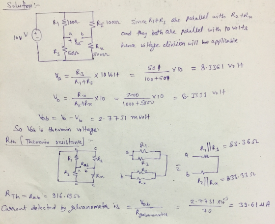
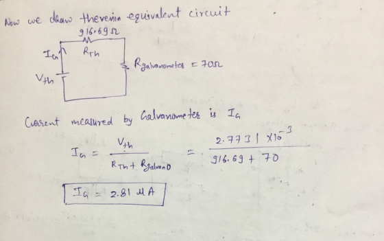
 Question 9 Given the Wheatstone bridge circuit in the figure below, determine VthA in Voits M the Thevenin voltage source for the branch A The unit must be given with along with the nuneric answer Vs 10 V R1 100 Ohm R2 275 Ohm R3 200 Ohm R4 150 Ohm RL = 956 Ohm R, R. Δ Moving to another question wil save this response
Part II: Wheatstone Bridge Procedure: 1) Before connecting the circuit, use the multi...
 Part
II: Wheatstone Bridge
Procedure:
1) Before connecting the
circuit, use the multimeter as an ohmeter to verify the values of
all the resistances. Use the voltmeter measure the terminal voltage
of the battery. Use these measured values in all calculations.
R1 = 100 Ω
R2 = 200 Ω
R3 = 300 Ω
R4 = 200 Ω
R5 = 20 Ω
ξ = 6 V
Connect the circuit shown using
the multimeter as the ammeter.
2) Use a voltmeter to...
Part
II: Wheatstone Bridge
Procedure:
1) Before connecting the
circuit, use the multimeter as an ohmeter to verify the values of
all the resistances. Use the voltmeter measure the terminal voltage
of the battery. Use these measured values in all calculations.
R1 = 100 Ω
R2 = 200 Ω
R3 = 300 Ω
R4 = 200 Ω
R5 = 20 Ω
ξ = 6 V
Connect the circuit shown using
the multimeter as the ammeter.
2) Use a voltmeter to...
 Part B. Wheatstone Bridge Circuit with a Current Source Is R5 R1 R2 Is RL R3 R4 For the circuit as shown below, given that R1-20 Ω,R2= 12 Ω, R3-18 Ω, R4= 20 Ω, R5= 9 Ω , R.-3 ΩΊ,-15 A. I. Wheatstone Bridge Circuit Analysis (a) Determining the load voltage VL-Vab for the Wheatstone bridge circuit with LTspice. Subrnit Answer Tries 0/3 (b) Determining the load current I following from a to b for the Wheatstone bridge circuit with...
 Mini-Prj 2. Extraction of Thevenin and Norton Equivalent Circuits by LTspice Part A. Wheatstone Bridge Circuit with a Voltage Source Vs R5 R1 R2 Vs RL R3 R4 For the circuit as shown below, given that R1= 9 Ω, R2= 17 Ω, R3= 9 Ω' R,-18 Ω, R5= 19 Ω , RL= 2 Ω ,V,-74 V I. Wheatstone Bridge Circuit Analysis (a) Determining the load voltage Vi-Vab for the Wheatstone bridge circuit with LTspice Submit Answer Tries 0/3 (b) Determining...
 8. Fig. 1 is a Wheatstone bridge circuit. No current flows through the galvanometer. You find Rx is d. 144 Ω b. 5Ω 1 296-02 12 6.0043 60 Voltage V
8. Fig. 1 is a Wheatstone bridge circuit. No current flows through the galvanometer. You find Rx is d. 144 Ω b. 5Ω 1 296-02 12 6.0043 60 Voltage V
8. Fig. 1 is a Wheatstone bridge circuit. No current flows through the galvanometer. You find Rx is d. 144 Ω b. 5Ω 1 296-02 12 6.0043 60 Voltage V
 7.- The Wheatstone Bridge. The circuit shown in the figure, called a Wheatstone bridge, is used to determine the value of an unknown resistor \(X\) by comparison with three resistors \(M, N\), and \(P\) whose resistances can be varied. For each setting, the resistance of each resistor is precisely known. With switches \(K_{1}\) and \(K_{2}\) closed, these resistors are varied until the current in the galvanometer \(G\) is zero; the bridge is then said to be balanced. (a) Show that...
 Mini-Prj 2. Extraction of Thevenin and Norton Equivalent Circuits by LTspice Part A. Wheatstone Bridge Circuit with a Voltage Source Vs R5 R1 R2 Vs RL R3 R4 For the circuit as shown below, given that R1= 9 Ω, R2= 17 Ω, R3= 9 Ω' R,-18 Ω, R5= 19 Ω , RL= 2 Ω ,V,-74 V I. Wheatstone Bridge Circuit Analysis (a) Determining the load voltage Vi-Vab for the Wheatstone bridge circuit with LTspice Submit Answer Tries 0/3 (b) Determining...
 Part A. Wheatstone Bridge Circuit with a Voltage Source Vs R5 R1 R2 Vs RL R3 R4 For the circuit as shown below, given that R1: 23 Ω, R2° 13 O, R,-230, R4% 3 Ω. RS: 28 Ω , RL: 13 Ω ,Vs-90 . I. Wheatstone Bridge Circuit Analysis (a) Determining the load voltage VL-Vab for the Wheatstone bridge circuit with LTspice 1 Submit Answer Tries 0/3 (b) Determining the load current I following from a to b for the...
 Mini-Prj 2. Extraction of Thevenin and Norton Equivalent Circuits by LTspice Part B. Wheatstone Bridge Circuit with a Current Source Is R5 R1 R2 Is RL R3 R4 For the circuit as shown below, given that R1-22 Ω, R2-15 Ω, R3-28 Ω, R4-9 Ω, R5-29 Ω , R.-16 Ω, 1,-6 A. I. Wheatstone Bridge Circuit Analysis (a) Determining the load voltage VL-Vab for the Wheatstone bridge circuit with LTspice. Submit Answer Tries 0/4 (b) Determining the load current IL following...
 This circuit is a Wheatstone Bridge. It is used for numerous
scientific and engineering applications. Here, R1 = 20 kΩ, R2 = 10
kΩ, R3 = 5 kΩ, and R4 = 10 kΩ. ε = 5 V.
a) Determine the Thevenin equivalent resistance RTH between
points A and B. (Hint: when we remove the power supply and short
the circuit, the wire connecting the “top” and “bottom” of the
bridge can then be drawn to go right down the center...
This circuit is a Wheatstone Bridge. It is used for numerous
scientific and engineering applications. Here, R1 = 20 kΩ, R2 = 10
kΩ, R3 = 5 kΩ, and R4 = 10 kΩ. ε = 5 V.
a) Determine the Thevenin equivalent resistance RTH between
points A and B. (Hint: when we remove the power supply and short
the circuit, the wire connecting the “top” and “bottom” of the
bridge can then be drawn to go right down the center...
 Question 9 Given the Wheatstone bridge circuit in the figure below, determine VthA in Voits M the Thevenin voltage source for the branch A The unit must be given with along with the nuneric answer Vs 10 V R1 100 Ohm R2 275 Ohm R3 200 Ohm R4 150 Ohm RL = 956 Ohm R, R. Δ Moving to another question wil save this response
 Part
II: Wheatstone Bridge
Procedure:
1) Before connecting the
circuit, use the multimeter as an ohmeter to verify the values of
all the resistances. Use the voltmeter measure the terminal voltage
of the battery. Use these measured values in all calculations.
R1 = 100 Ω
R2 = 200 Ω
R3 = 300 Ω
R4 = 200 Ω
R5 = 20 Ω
ξ = 6 V
Connect the circuit shown using
the multimeter as the ammeter.
2) Use a voltmeter to...
Part
II: Wheatstone Bridge
Procedure:
1) Before connecting the
circuit, use the multimeter as an ohmeter to verify the values of
all the resistances. Use the voltmeter measure the terminal voltage
of the battery. Use these measured values in all calculations.
R1 = 100 Ω
R2 = 200 Ω
R3 = 300 Ω
R4 = 200 Ω
R5 = 20 Ω
ξ = 6 V
Connect the circuit shown using
the multimeter as the ammeter.
2) Use a voltmeter to...
Most questions answered within 3 hours.
-
Under the influence of its drive force, a snowmobile is moving
at a constant velocity along...
asked 1 hour ago -
Why do organizations decline? What steps can top
management take to halt, decline, and restore organizational...
asked 1 hour ago -
. Suppose a discrete random variable has probability
distribution
P(x) = .2 if x = 0...
asked 59 minutes ago -
What mechanisms Drive speciation??
(I.e. what was Dawins theory on the orgin of species, and how...
asked 2 hours ago -
The manager at a car assembly plant believes that the mean
assembly time for a car...
asked 3 hours ago -
Which of the following is true of electron capture?
A) It decreases the nuclide's mass number...
asked 5 hours ago -
Assuming an efficiency of 43.10%, calculate the actual yield of
magnesium nitrate formed from 114.9 g...
asked 5 hours ago -
The highly pathogenic bacterium Clostridium
perfringens causes gangrene, a disease that results in the
destruction of...
asked 7 hours ago -
In the context of situation analysis, which of the following is
a category for analysis in...
asked 7 hours ago -
In a study of the gas phase decomposition of sulfuryl chloride
at 600 K SO2Cl2(g)SO2(g) +...
asked 7 hours ago -
75 g of 2-propanol (C3H8O) and 25 g of pentane are mixed in a
200 mL...
asked 7 hours ago -
The 2800-turn coil in a dc motor has an area per turn of 1.1 ×
10-2...
asked 7 hours ago