
Homework Answers
NOTE:
ALL ANSWERS GIVEN ARE WRONG.
------------------------------------------
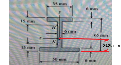
The normal stress at K is comprised of:
- Direct Axial Stress
- Bending Stress
Direct Axial Stress = 
where
- P = force = +10.2 kN = + 10200 N
- Area = Area of cross-section =


Bending Stress = 
where
- M = Bending Moment = -2.1 kN.m = -2.1e6 N.mm [Compressive Stress will act]
- y = distance of point K from centroid =

- I(zz) = Area moment of inertia = 511283 mm4


TOTAL NORMAL STRESS AT K = -58.694 + 12.318 = -46.376 MPa
----------------------------------------
As we can see, all the options given are wrong. But then, I have a strong feeling the answer is OPTION A.
I found that if we half the obtained answer, 
----------------------------------------
I have checked my answer repeatedly. In case you happen to find any error that I have done, please feel free to ping in the comments. But other than that, I feel all the answers are wrong.
Kindly upvote in case I had/have helped you with the right answer. :)
Add Answer to:
- how Attempt History Current Attempt in Progress X Your answer is incorrect. Aflanged-shaped flexural member...
A tee-shaped flexural member is subjected to an internal axial force of P = 4,000 N,...
 A tee-shaped flexural member is subjected to an internal axial
force of P = 4,000 N, an internal shear force of
V = 3500 N, and an internal bending moment of M =
1770 N-m, as shown. If the moment of inertia about the z
axis is 8,840,000 mm4 and the centroid of the section is
located 95 mm above the bottom surface of the beam, determine the
normal stress σy at point H.
-0.412 MPa
-0.615 MPa
0.000 MPa...
A tee-shaped flexural member is subjected to an internal axial
force of P = 4,000 N, an internal shear force of
V = 3500 N, and an internal bending moment of M =
1770 N-m, as shown. If the moment of inertia about the z
axis is 8,840,000 mm4 and the centroid of the section is
located 95 mm above the bottom surface of the beam, determine the
normal stress σy at point H.
-0.412 MPa
-0.615 MPa
0.000 MPa...
Do all questions that are wrong or unfilled and please circle answers Chapter 12, Reserve Problem...
 Do all questions that are wrong or unfilled
and please circle answers
Chapter 12, Reserve Problem 052 (Multistep) Part 1 Correct A flanged-shaped flexural member is subjected to an internal axial force of 17.9 kN, an internal shear force of 12.0 kN, and an internal bending moment of 1.9 kN-m, as shown. Assume b = 34 mm, b2 = 52 mm, dy = dx = 13 mm, ti = ta = ty = 7 mm, d = 65 mm. Determine...
Do all questions that are wrong or unfilled
and please circle answers
Chapter 12, Reserve Problem 052 (Multistep) Part 1 Correct A flanged-shaped flexural member is subjected to an internal axial force of 17.9 kN, an internal shear force of 12.0 kN, and an internal bending moment of 1.9 kN-m, as shown. Assume b = 34 mm, b2 = 52 mm, dy = dx = 13 mm, ti = ta = ty = 7 mm, d = 65 mm. Determine...
M15.3 Principal stresses in a rectangular tube scenes The rectangular tube is subjected to a transverse shear force of...
 M15.3 Principal stresses in a rectangular tube scenes The rectangular tube is subjected to a transverse shear force of V = 230 kN and a bending moment of M = 530 kN-m, each acting in the directions shown. Determine the bending stress, the transverse shear stress magnitude, the principal stresses, and the maximum shear stress magnitude acting at location H. У Он (MPa) H 550 mm TH (MPa) 65 mm Op1 (MPa) X Op2 (MPa) 12 mm ITmax (MPa) wall...
please show how they got the answers also please show how they found Qh becuse it...
 please show how they got the answers also please show how they
found Qh becuse it is not given.
scenes M15.2 Principal stresses in a tee beam The inverted tee shape is subjected to a transverse shear force of V = 110 kN and a bending moment of M = 50 kN-m, each acting in the directions shown. Determine the bending stress, the transverse shear stress magnitude, the principal stresses, and the maximum shear stress acting at location H. 14...
please show how they got the answers also please show how they
found Qh becuse it is not given.
scenes M15.2 Principal stresses in a tee beam The inverted tee shape is subjected to a transverse shear force of V = 110 kN and a bending moment of M = 50 kN-m, each acting in the directions shown. Determine the bending stress, the transverse shear stress magnitude, the principal stresses, and the maximum shear stress acting at location H. 14...
The flanged member shown below is subjected to an internal axial force of P = 6500...
 The flanged member shown below is subjected to an internal axial force of P = 6500 lb, an internal shear force of V = 4500 lb, and an internal bending moment of M = 19200 lb-ft, acting in the directions shown. d M Iw y HI a y Ilk thu The dimensions of the cross section are: bf = 8.0 in. tp = 0.61 in. d = 11.0 in. tw = 0.38 in. The cross-sectional area of the flanged shape...
Review Learning Goal: To use the superposition principle to find the state of stress on a...
 Review Learning Goal: To use the superposition principle to find the state of stress on a beam under multiple loadings The beam shown below is subjected to a horizontal force P via the rope wound around the pulley. The state of stress at point A is to be determined. Part A - Support Reactions and Internal Loading Determine the support reactions Cy and Cz and the internal normal force, shear force, and moment on the cross-section containing point A. Express...
Part A - Support Reactions and Internal Loading Learning Goal: To use the superposition principle to...
 Part A - Support Reactions and Internal Loading Learning Goal: To use the superposition principle to find the state of stress on a beam under multiple loadings. The beam shown below is subjected to a horizontal force P via the rope wound around the pulley. The state of stress at point A is to be determined Determine the support reactions Cy and Cand the internal normal force, shear force, and moment on the cross-section containing point A Express your answers,...
Learning Goal: To use the superposition principle to find the state of stress on a beam...
 Learning Goal: To use the superposition principle to find the state of stress on a beam under multiple loadings. The beam shown below is subjected to a horizontal force P via the rope wound around the pulley. The state of stress at point A is to be determined. P 1d4 di dz d2 20 mm T 100 mm 200 mm 15 mm 20 mm 150 mm The dimensions are di = 1.85 m, d2 = 0.5 m, dz = 0.9...
Sm 100 mm Consider the flat bar with shoulder joints shown in Fig. A which is...
 Sm 100 mm Consider the flat bar with shoulder joints shown in Fig. A which is subjected to a tensile force P-58 kN. The bar is made of Aluminum 6061 having maximum tensile strength Omar = 290 MPa. NOTE: plots of stress concentration factors for different types of loading can be found on page 6 (a) Determine the radiusr [mm] for the fillets. (b) An identical flat bar shown in Fig. B replaces the tensile load with a bending moment...
above provided question with answer... So using that solve below question so solve this question....I'm provided...
 above provided question with
answer...
So using that solve below question
so solve this question....I'm
provided sample question with answer too
Same process values are changed...
I will give positive rating
(b) Calculate the maximum in-plane shear stress Imax on the outer surface of the pipe at point kif there is an internal pressure of 3600 kPa inside the pipe. (Note: Enter the absolute value here.) Tax for point- MPa For this analysis, use the following values: Distances, Loads, and...
above provided question with
answer...
So using that solve below question
so solve this question....I'm
provided sample question with answer too
Same process values are changed...
I will give positive rating
(b) Calculate the maximum in-plane shear stress Imax on the outer surface of the pipe at point kif there is an internal pressure of 3600 kPa inside the pipe. (Note: Enter the absolute value here.) Tax for point- MPa For this analysis, use the following values: Distances, Loads, and...
 A tee-shaped flexural member is subjected to an internal axial
force of P = 4,000 N, an internal shear force of
V = 3500 N, and an internal bending moment of M =
1770 N-m, as shown. If the moment of inertia about the z
axis is 8,840,000 mm4 and the centroid of the section is
located 95 mm above the bottom surface of the beam, determine the
normal stress σy at point H.
-0.412 MPa
-0.615 MPa
0.000 MPa...
A tee-shaped flexural member is subjected to an internal axial
force of P = 4,000 N, an internal shear force of
V = 3500 N, and an internal bending moment of M =
1770 N-m, as shown. If the moment of inertia about the z
axis is 8,840,000 mm4 and the centroid of the section is
located 95 mm above the bottom surface of the beam, determine the
normal stress σy at point H.
-0.412 MPa
-0.615 MPa
0.000 MPa...
 Do all questions that are wrong or unfilled
and please circle answers
Chapter 12, Reserve Problem 052 (Multistep) Part 1 Correct A flanged-shaped flexural member is subjected to an internal axial force of 17.9 kN, an internal shear force of 12.0 kN, and an internal bending moment of 1.9 kN-m, as shown. Assume b = 34 mm, b2 = 52 mm, dy = dx = 13 mm, ti = ta = ty = 7 mm, d = 65 mm. Determine...
Do all questions that are wrong or unfilled
and please circle answers
Chapter 12, Reserve Problem 052 (Multistep) Part 1 Correct A flanged-shaped flexural member is subjected to an internal axial force of 17.9 kN, an internal shear force of 12.0 kN, and an internal bending moment of 1.9 kN-m, as shown. Assume b = 34 mm, b2 = 52 mm, dy = dx = 13 mm, ti = ta = ty = 7 mm, d = 65 mm. Determine...
 M15.3 Principal stresses in a rectangular tube scenes The rectangular tube is subjected to a transverse shear force of V = 230 kN and a bending moment of M = 530 kN-m, each acting in the directions shown. Determine the bending stress, the transverse shear stress magnitude, the principal stresses, and the maximum shear stress magnitude acting at location H. У Он (MPa) H 550 mm TH (MPa) 65 mm Op1 (MPa) X Op2 (MPa) 12 mm ITmax (MPa) wall...
 please show how they got the answers also please show how they
found Qh becuse it is not given.
scenes M15.2 Principal stresses in a tee beam The inverted tee shape is subjected to a transverse shear force of V = 110 kN and a bending moment of M = 50 kN-m, each acting in the directions shown. Determine the bending stress, the transverse shear stress magnitude, the principal stresses, and the maximum shear stress acting at location H. 14...
please show how they got the answers also please show how they
found Qh becuse it is not given.
scenes M15.2 Principal stresses in a tee beam The inverted tee shape is subjected to a transverse shear force of V = 110 kN and a bending moment of M = 50 kN-m, each acting in the directions shown. Determine the bending stress, the transverse shear stress magnitude, the principal stresses, and the maximum shear stress acting at location H. 14...
 The flanged member shown below is subjected to an internal axial force of P = 6500 lb, an internal shear force of V = 4500 lb, and an internal bending moment of M = 19200 lb-ft, acting in the directions shown. d M Iw y HI a y Ilk thu The dimensions of the cross section are: bf = 8.0 in. tp = 0.61 in. d = 11.0 in. tw = 0.38 in. The cross-sectional area of the flanged shape...
 Review Learning Goal: To use the superposition principle to find the state of stress on a beam under multiple loadings The beam shown below is subjected to a horizontal force P via the rope wound around the pulley. The state of stress at point A is to be determined. Part A - Support Reactions and Internal Loading Determine the support reactions Cy and Cz and the internal normal force, shear force, and moment on the cross-section containing point A. Express...
 Part A - Support Reactions and Internal Loading Learning Goal: To use the superposition principle to find the state of stress on a beam under multiple loadings. The beam shown below is subjected to a horizontal force P via the rope wound around the pulley. The state of stress at point A is to be determined Determine the support reactions Cy and Cand the internal normal force, shear force, and moment on the cross-section containing point A Express your answers,...
 Learning Goal: To use the superposition principle to find the state of stress on a beam under multiple loadings. The beam shown below is subjected to a horizontal force P via the rope wound around the pulley. The state of stress at point A is to be determined. P 1d4 di dz d2 20 mm T 100 mm 200 mm 15 mm 20 mm 150 mm The dimensions are di = 1.85 m, d2 = 0.5 m, dz = 0.9...
 Sm 100 mm Consider the flat bar with shoulder joints shown in Fig. A which is subjected to a tensile force P-58 kN. The bar is made of Aluminum 6061 having maximum tensile strength Omar = 290 MPa. NOTE: plots of stress concentration factors for different types of loading can be found on page 6 (a) Determine the radiusr [mm] for the fillets. (b) An identical flat bar shown in Fig. B replaces the tensile load with a bending moment...
 above provided question with
answer...
So using that solve below question
so solve this question....I'm
provided sample question with answer too
Same process values are changed...
I will give positive rating
(b) Calculate the maximum in-plane shear stress Imax on the outer surface of the pipe at point kif there is an internal pressure of 3600 kPa inside the pipe. (Note: Enter the absolute value here.) Tax for point- MPa For this analysis, use the following values: Distances, Loads, and...
above provided question with
answer...
So using that solve below question
so solve this question....I'm
provided sample question with answer too
Same process values are changed...
I will give positive rating
(b) Calculate the maximum in-plane shear stress Imax on the outer surface of the pipe at point kif there is an internal pressure of 3600 kPa inside the pipe. (Note: Enter the absolute value here.) Tax for point- MPa For this analysis, use the following values: Distances, Loads, and...
Most questions answered within 3 hours.
-
A business executive has the option to invest money in two
plans: Plan A guarantees that...
asked 40 minutes ago -
Hello, can someone please help me answer this question?
How much heat is absorbed by a...
asked 38 minutes ago -
. A marketing researcher conducted a survey of 25 shoppers
randomly selected at the local mall...
asked 55 minutes ago -
Create an comprehensive response to the
following:
Antimicrobial agents work on a multitude of microbes (bacteria,...
asked 56 minutes ago -
6.13 LAB: Step counter. Section 6.3.
A pedometer treats walking 2,000 steps as walking 1 mile....
asked 52 minutes ago -
(14.2) A block of mass m = 10 kg riding on a frictionless
horizontal plane is...
asked 55 minutes ago -
Use any search engine to search for articles about Starbucks
partnership with Tata Companies in India...
asked 53 minutes ago -
Let’s say that for some reason Bank Excess Reserves suddenly
increase sharply. What effect would this...
asked 1 hour ago -
Given:
Curent Assets: $600,000
Total Assets: $2,600,000
Current Liabilities: $500,000
Total Liabilities: $1,700,000
What is the...
asked 1 hour ago -
1. What is a “Bankster”? What is insider trading? Why is it
illegal?
2. What is...
asked 1 hour ago -
A transverse wave on a cord is given by
D(x,t)=0.18sin(2.7x−61.0t), where Dand x are in m...
asked 1 hour ago -
ASSIGNMENT
ANSWER ANY TWO OF THE FOLLOWING IN 2-3 PARAGRAPHS OF EACH
QUESTION.
1: Where is...
asked 1 hour ago