
Homework Answers

Add Answer to:
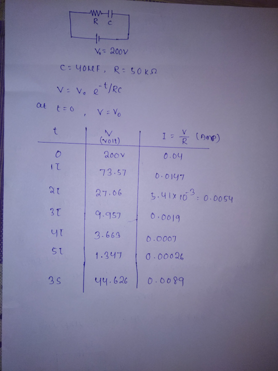
с 4) If R= 50kr and c=40 KF an calculate vand i at tzo, 0-2000 12,...
q R ww С I Switch Question 4: Suppose R 270 k2, C = 820 jF...
 q R ww С I Switch Question 4: Suppose R 270 k2, C = 820 jF in Figure 4in section 6.2, calculate the voltage across the capacitor, 37 seconds after the resistor is connected across the charged capacitor. The capacitor is initially charged to 9 volts. 820 Fin Figure |4|in section 62., calculate the time Question 5: Suppose R constant of the circuit. The capacitor is initially charged to 9 volts 270 k, C
Question 4. Refer to the circuit of Figure 4. R 802 50 uF с vi(t) v.(t)...
 Question 4. Refer to the circuit of Figure 4. R 802 50 uF с vi(t) v.(t) Figure 4 a) Draw the circuit in the Laplace domain, and then apply basic circuit theory in the Laplace domain to show that the Laplace transfer function H(s) defined for this system is: HS) V.(5) V (5) sta where a= RC [8 Marks] b) Use Laplace methods to determine the output voltage vo(t) when the input voltage is defined as: v (1) 40(1) The...
Use Thevenin’s theorem to calculate a, b, c, d and e only a) The current through...
 Use
Thevenin’s theorem to calculate a, b, c, d and e only
a) The current through the load resistor (I); b) The voltage across the load resistor (V): c) I short circuit (I); d) V open circuit (V). This is the Thevenin voltage (E); .) The resistance (R) between the terminals A and B with the power supplies replaced by their internal resistances. This is the Thevenin resistance (R ). 2. Using the values obtained in Part 1 for E...
Use
Thevenin’s theorem to calculate a, b, c, d and e only
a) The current through the load resistor (I); b) The voltage across the load resistor (V): c) I short circuit (I); d) V open circuit (V). This is the Thevenin voltage (E); .) The resistance (R) between the terminals A and B with the power supplies replaced by their internal resistances. This is the Thevenin resistance (R ). 2. Using the values obtained in Part 1 for E...
In the figure, R - 12 A, C 8 MF, and 2 - 3 m, and...
 In the figure, R - 12 A, C 8 MF, and 2 - 3 m, and the ideal battery has emf - 32 V. The switch is kept in position a for a long time and then thrown to position b. What are w HE R b HE С L 2000 (a) the maximum charge in the capacitor plates? In the figure, R = 122, C-8 and 2 - 3 m, and the ideal battery has ent - 32 V....
For the circuit shown in Figure 3. С + HC If Z 1.8 nF 1.8 nF...
 For the circuit shown in Figure 3. С + HC If Z 1.8 nF 1.8 nF 1.8 nF + I = 4 mA 20° 0 R 2.2 k.12 R2 2.2 k 12 R3 2.2 kΩ V, R f = 40 kHz Figure 3 a. Find the total impedance ZT b. Find the voltage across the resistor R3
05. If, for all time t, v(t)-12 V, R-6.C2F, and i(t)-0A, the voltage y(t) (in volts)...
 05. If, for all time t, v(t)-12 V, R-6.C2F, and i(t)-0A, the voltage y(t) (in volts) across the capacitor is 09. If v() 8Vand i. (t) 2 A, the power in watts) being absorbed by the time to 1S 2. -12 3. 2 2. 16 s 0 4. 4 5. -16 5. 144 06. If, for all time t, i.(t) 8A, R-8OL-2H and v(t)-0 V, the current i(t) (in amperes) through the inductor is 10. IfV.-12 V andI.-2 A, the...
AME: 2. (24pts) Consider the curve given in polar coordinates by r-12 cos(0) Vsin(0), (0 0...
 AME: 2. (24pts) Consider the curve given in polar coordinates by r-12 cos(0) Vsin(0), (0 0 < #). (i) Make a table of the values of the function f(0)--12 cos(0)/sin(0) /6 /4 n/3 5m/12 m/2 7m/12 2n/3 3n/4 5n/6 11 m/12 f(0) are to be rounded to two decimal places. (Hint. Given on 0, r); all the values f(0) an angle 9, enter the value of 0 to the variable C of your calculator, and then evaluate /(0) using the...
3. Natural response, for ? > 0 of a series R-L-C circuit has R = 1...
3. Natural response, for ? > 0 of a series R-L-C circuit has R = 1 Ω , L = 1 H and C = 1 F. The initial capacitor voltage is 4 V, and initial inductor current is zero. The series current is i. (i) Draw the time domain circuit. (ii) Draw the Laplace transform domain circuit. (iii) From (ii), determine Io =Io (s) (iv) From (iii), determine ?? = ??(?) for t > 0
please take y = 4 5. For the circuit given in Figure 5, a) Calculate the...
 please take y = 4
5. For the circuit given in Figure 5, a) Calculate the equivalent load impedance seen by the voltage source (reflected from secondary to primary). b) Calculate the primary current and voltage of the transformer. c) Calculate the secondary current and voltage of the transformer. Here, Rư= The largest value of the last 3 digits of your school number. Lı = The smallest value of the last 3 digits of your school number. If the smallest...
please take y = 4
5. For the circuit given in Figure 5, a) Calculate the equivalent load impedance seen by the voltage source (reflected from secondary to primary). b) Calculate the primary current and voltage of the transformer. c) Calculate the secondary current and voltage of the transformer. Here, Rư= The largest value of the last 3 digits of your school number. Lı = The smallest value of the last 3 digits of your school number. If the smallest...
4. An inductor of inductance L= 15 H is charged through a resistor of resistance R=5...
 4. An inductor of inductance L= 15 H is charged through a resistor of resistance R=5 W by a battery of voltage V= 20 Volts. The current as a function of time during charging of this inductor is represented in the table below. The equation of current versus time is also represented by I(t)=L(1 - exp(-t/t) ), where L =V/R, and t = L/R. By taking In of both sides of the current equation, one could linearize it as: In(I-I(t))...
 q R ww С I Switch Question 4: Suppose R 270 k2, C = 820 jF in Figure 4in section 6.2, calculate the voltage across the capacitor, 37 seconds after the resistor is connected across the charged capacitor. The capacitor is initially charged to 9 volts. 820 Fin Figure |4|in section 62., calculate the time Question 5: Suppose R constant of the circuit. The capacitor is initially charged to 9 volts 270 k, C
 Question 4. Refer to the circuit of Figure 4. R 802 50 uF с vi(t) v.(t) Figure 4 a) Draw the circuit in the Laplace domain, and then apply basic circuit theory in the Laplace domain to show that the Laplace transfer function H(s) defined for this system is: HS) V.(5) V (5) sta where a= RC [8 Marks] b) Use Laplace methods to determine the output voltage vo(t) when the input voltage is defined as: v (1) 40(1) The...
 Use
Thevenin’s theorem to calculate a, b, c, d and e only
a) The current through the load resistor (I); b) The voltage across the load resistor (V): c) I short circuit (I); d) V open circuit (V). This is the Thevenin voltage (E); .) The resistance (R) between the terminals A and B with the power supplies replaced by their internal resistances. This is the Thevenin resistance (R ). 2. Using the values obtained in Part 1 for E...
Use
Thevenin’s theorem to calculate a, b, c, d and e only
a) The current through the load resistor (I); b) The voltage across the load resistor (V): c) I short circuit (I); d) V open circuit (V). This is the Thevenin voltage (E); .) The resistance (R) between the terminals A and B with the power supplies replaced by their internal resistances. This is the Thevenin resistance (R ). 2. Using the values obtained in Part 1 for E...
 In the figure, R - 12 A, C 8 MF, and 2 - 3 m, and the ideal battery has emf - 32 V. The switch is kept in position a for a long time and then thrown to position b. What are w HE R b HE С L 2000 (a) the maximum charge in the capacitor plates? In the figure, R = 122, C-8 and 2 - 3 m, and the ideal battery has ent - 32 V....
 For the circuit shown in Figure 3. С + HC If Z 1.8 nF 1.8 nF 1.8 nF + I = 4 mA 20° 0 R 2.2 k.12 R2 2.2 k 12 R3 2.2 kΩ V, R f = 40 kHz Figure 3 a. Find the total impedance ZT b. Find the voltage across the resistor R3
 05. If, for all time t, v(t)-12 V, R-6.C2F, and i(t)-0A, the voltage y(t) (in volts) across the capacitor is 09. If v() 8Vand i. (t) 2 A, the power in watts) being absorbed by the time to 1S 2. -12 3. 2 2. 16 s 0 4. 4 5. -16 5. 144 06. If, for all time t, i.(t) 8A, R-8OL-2H and v(t)-0 V, the current i(t) (in amperes) through the inductor is 10. IfV.-12 V andI.-2 A, the...
 AME: 2. (24pts) Consider the curve given in polar coordinates by r-12 cos(0) Vsin(0), (0 0 < #). (i) Make a table of the values of the function f(0)--12 cos(0)/sin(0) /6 /4 n/3 5m/12 m/2 7m/12 2n/3 3n/4 5n/6 11 m/12 f(0) are to be rounded to two decimal places. (Hint. Given on 0, r); all the values f(0) an angle 9, enter the value of 0 to the variable C of your calculator, and then evaluate /(0) using the...
 please take y = 4
5. For the circuit given in Figure 5, a) Calculate the equivalent load impedance seen by the voltage source (reflected from secondary to primary). b) Calculate the primary current and voltage of the transformer. c) Calculate the secondary current and voltage of the transformer. Here, Rư= The largest value of the last 3 digits of your school number. Lı = The smallest value of the last 3 digits of your school number. If the smallest...
please take y = 4
5. For the circuit given in Figure 5, a) Calculate the equivalent load impedance seen by the voltage source (reflected from secondary to primary). b) Calculate the primary current and voltage of the transformer. c) Calculate the secondary current and voltage of the transformer. Here, Rư= The largest value of the last 3 digits of your school number. Lı = The smallest value of the last 3 digits of your school number. If the smallest...
 4. An inductor of inductance L= 15 H is charged through a resistor of resistance R=5 W by a battery of voltage V= 20 Volts. The current as a function of time during charging of this inductor is represented in the table below. The equation of current versus time is also represented by I(t)=L(1 - exp(-t/t) ), where L =V/R, and t = L/R. By taking In of both sides of the current equation, one could linearize it as: In(I-I(t))...
Most questions answered within 3 hours.
-
Suppose we have a binomial experiment in which success is
defined to be a particular quality...
asked 13 minutes ago -
march the type of cellular control with the description: enzyme
induction and the enzyme repression. How...
asked 22 minutes ago -
Brief Exercise 5-09 (Part Level Submission)
The following information relates to Blue Spruce Corp. for the...
asked 22 minutes ago -
An unknown amount of a compound with a molecular mass of 284.04
g/mol is dissolved in...
asked 28 minutes ago -
You are at rest at a stop sign. There is another stop sign that
is 100...
asked 29 minutes ago -
Calculate the equilibrium electrode potential for Fe3+/Fe2+
redox system, if the initial concentration of Fe2+ is...
asked 32 minutes ago -
Describe in detail with graph and diagram how bonding force,
bonding curves and bonding energy at...
asked 49 minutes ago -
Gingerbread cookies become inedible if not eaten quickly enough.
Clarence is trying to determine how many...
asked 45 minutes ago -
A
crane lifts a 200 kg block a height of 10 m in 18 seconds. What...
asked 48 minutes ago -
A 12.0-g bullet is fired horizontally into a 115-g wooden block
that is initially at rest...
asked 48 minutes ago -
Which DNA primer would have the HIGHEST melting temperature?
Question 17 options:
a)
GCATCGGC
b)
AATCGGAT...
asked 56 minutes ago -
what is the charge on the chromium ion in Cr2O3.
a -3
b -2
c 0...
asked 56 minutes ago