


Homework Answers


![Efy=0. 4-Rzo k:ч ойр EM2=0 urip (56+ ] _M2=0 Mz= 304 kep in {Mx=0 ukip [32+26] Mx=0 Mx = 180kip.in Find the normal stress at](http://img.homeworklib.com/questions/06e8a090-568e-11eb-8cf1-09cb152124e4.png?x-oss-process=image/resize,w_560)
Add Answer to:
Only point A please
HOMEWORK 1: At the Cullowhee Zoo one of the most popular attractions...
What stresses would you need to calculate in order to develop the 2D state of stress for point B on the cross section of the pipe assembly 400 mm al 200 mm 1500 N 1000 N 20 mm Section a-a a. Normal s...
 What stresses would you need to calculate in order to develop the 2D state of stress for point B on the cross section of the pipe assembly 400 mm al 200 mm 1500 N 1000 N 20 mm Section a-a a. Normal stress due to normal force, normal stress due to bending moment b. Shear stress due to shear force, normal stress due to normal force, normal stress due to bending moment due to normal force, normal stress due to...
The beam shown (Figure 1) is supported by a pin at A and a cable at...
 The beam shown (Figure 1) is
supported by a pin at A and a cable at B. Two
loads P = 13 kN are applied straight down from the
centerline of the bottom face. Determine the state of stress at the
point shown (Figure 2) in a section 2 m from the wall. The
dimensions are w = 5.2 cm , h = 10.5 cm ,
L = 0.8 m , a = 1.5 cm , and b = 4...
The beam shown (Figure 1) is
supported by a pin at A and a cable at B. Two
loads P = 13 kN are applied straight down from the
centerline of the bottom face. Determine the state of stress at the
point shown (Figure 2) in a section 2 m from the wall. The
dimensions are w = 5.2 cm , h = 10.5 cm ,
L = 0.8 m , a = 1.5 cm , and b = 4...
The beam shown (Figure 1) is supported by a pin at A and a cable at...
 The beam shown (Figure 1) is supported by a pin at A
and a cable at B. Two loads P = 13 kN are applied
straight down from the centerline of the bottom face. Determine the
state of stress at the point shown (Figure 2) in a section 2 m from
the wall. The dimensions are w = 5.2 cm , h =
10.5 cm , L = 0.8 m , a = 1.5 cm , and b
= 4...
The beam shown (Figure 1) is supported by a pin at A
and a cable at B. Two loads P = 13 kN are applied
straight down from the centerline of the bottom face. Determine the
state of stress at the point shown (Figure 2) in a section 2 m from
the wall. The dimensions are w = 5.2 cm , h =
10.5 cm , L = 0.8 m , a = 1.5 cm , and b
= 4...
The beam shown (Figure 1) is supported by a pin at A and a cable at...
 The beam shown (Figure 1) is supported by a pin at A and a cable at
B. Two loads P = 13 kN are applied straight down
from the centerline of the bottom face. Determine the state of
stress at the point shown (Figure 2) in a section 2 m from the
wall. The dimensions are w = 5.2 cm , h = 10.5 cm
, L = 0.8 m , a = 1.5 cm , and b = 4...
The beam shown (Figure 1) is supported by a pin at A and a cable at
B. Two loads P = 13 kN are applied straight down
from the centerline of the bottom face. Determine the state of
stress at the point shown (Figure 2) in a section 2 m from the
wall. The dimensions are w = 5.2 cm , h = 10.5 cm
, L = 0.8 m , a = 1.5 cm , and b = 4...
Learning Goal: The beam shown (Figure 1) is supported by a pin at A and a...
 Learning Goal: The beam shown (Figure 1) is supported by a pin at A and a cable at B. Two loads P = 18 kN are applied straight down from the centerline of the bottom face. Determine the state of stress at the point shown (Figure 2) in a section 2 m from the wall. The dimensions are w = 5.4 cm , h = 12 cm, L = 0.8 m, a = 1.5 cm , and b = 4...
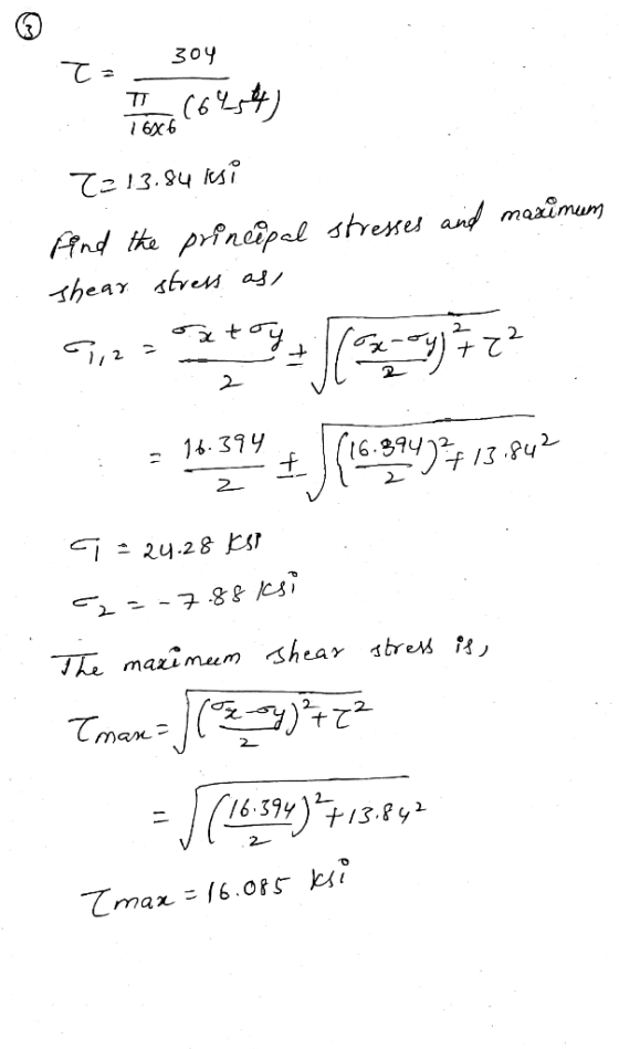
Question 5 16 pts The steel pipe AB has a 72-mm outer diameter and a 5-mm...
 Question 5 16 pts The steel pipe AB has a 72-mm outer diameter and a 5-mm wall thickness. Knowing that the arm CDE is rigidly attached to the pipe, determine the normal and shearing stresses at point H on the outer surface. The properties at the cross section at H include: A 1052.4 mm2,J 1,187,700 mm4, 1 593,840 mm4, and QNA 11,243 mm3 3 kN 9 kN 120 mm 150 mm 120 mm a.) Normal stress at H: b.) Shear...
15 Section 5, Problem 15 (25 pts.). A member is loaded by forces a, cand d...
 15 Section 5, Problem 15 (25 pts.). A member is loaded by forces a, cand d as shown. The member is a hollow member with an outer radius of ro and a wall thickness of t. The member is fixed at ground level where points Fand G occur. Determine: a) the normal and shear stress at point F. b) the normal and shear stress point 02:46:29 Forces: a = 30 (k),c=16 (k), and -17 (K) Dimensions: e = 32 (in.),...
Learning Goal: To calculate the normal and shear stresses at a point on the cross section...
 Learning Goal: To calculate the normal and shear stresses at a point on the cross section of a column. The state of stress at a point is a description of the normal and shear stresses at that point. The normal stresses are generally due to both internal normal force and internal bending moment. The net result can be obtained using the principle of superposition as long as the deflections remain small and the response is elastic. Figure < 1 of...
will upvote thank you! please try and be as detailed as possible to further my understanding...
 will upvote thank you! please try and be as detailed as
possible to further my understanding
Learning Goal: To calculate the normal and shear stresses at a point on the cross section of a column. The state of stress at a point is a description of the normal and shear stresses at that point. The normal stresses are generally due to both internal normal force and internal bending moment. The net result can be obtained using the principle of superposition...
will upvote thank you! please try and be as detailed as
possible to further my understanding
Learning Goal: To calculate the normal and shear stresses at a point on the cross section of a column. The state of stress at a point is a description of the normal and shear stresses at that point. The normal stresses are generally due to both internal normal force and internal bending moment. The net result can be obtained using the principle of superposition...
Q2: One side of a petrol drill pipe, as shown in the figure, has been lifted...
 Q2: One side of a petrol drill pipe, as shown in the figure, has been lifted with the use of a crane P force. The outer diameter of the pipe is do=114 mm and the inner diameter is di=92 mm. The total length of the pipe is L=9 m. The weight of the unit length of the pipe is q=280 N/m. For the inclination angle of the pipe axis 6=30°, (a) Draw the cross-sectional diagram of the pipe, (b) Find...
 What stresses would you need to calculate in order to develop the 2D state of stress for point B on the cross section of the pipe assembly 400 mm al 200 mm 1500 N 1000 N 20 mm Section a-a a. Normal stress due to normal force, normal stress due to bending moment b. Shear stress due to shear force, normal stress due to normal force, normal stress due to bending moment due to normal force, normal stress due to...
 The beam shown (Figure 1) is
supported by a pin at A and a cable at B. Two
loads P = 13 kN are applied straight down from the
centerline of the bottom face. Determine the state of stress at the
point shown (Figure 2) in a section 2 m from the wall. The
dimensions are w = 5.2 cm , h = 10.5 cm ,
L = 0.8 m , a = 1.5 cm , and b = 4...
The beam shown (Figure 1) is
supported by a pin at A and a cable at B. Two
loads P = 13 kN are applied straight down from the
centerline of the bottom face. Determine the state of stress at the
point shown (Figure 2) in a section 2 m from the wall. The
dimensions are w = 5.2 cm , h = 10.5 cm ,
L = 0.8 m , a = 1.5 cm , and b = 4...
 The beam shown (Figure 1) is supported by a pin at A
and a cable at B. Two loads P = 13 kN are applied
straight down from the centerline of the bottom face. Determine the
state of stress at the point shown (Figure 2) in a section 2 m from
the wall. The dimensions are w = 5.2 cm , h =
10.5 cm , L = 0.8 m , a = 1.5 cm , and b
= 4...
The beam shown (Figure 1) is supported by a pin at A
and a cable at B. Two loads P = 13 kN are applied
straight down from the centerline of the bottom face. Determine the
state of stress at the point shown (Figure 2) in a section 2 m from
the wall. The dimensions are w = 5.2 cm , h =
10.5 cm , L = 0.8 m , a = 1.5 cm , and b
= 4...
 The beam shown (Figure 1) is supported by a pin at A and a cable at
B. Two loads P = 13 kN are applied straight down
from the centerline of the bottom face. Determine the state of
stress at the point shown (Figure 2) in a section 2 m from the
wall. The dimensions are w = 5.2 cm , h = 10.5 cm
, L = 0.8 m , a = 1.5 cm , and b = 4...
The beam shown (Figure 1) is supported by a pin at A and a cable at
B. Two loads P = 13 kN are applied straight down
from the centerline of the bottom face. Determine the state of
stress at the point shown (Figure 2) in a section 2 m from the
wall. The dimensions are w = 5.2 cm , h = 10.5 cm
, L = 0.8 m , a = 1.5 cm , and b = 4...
 Learning Goal: The beam shown (Figure 1) is supported by a pin at A and a cable at B. Two loads P = 18 kN are applied straight down from the centerline of the bottom face. Determine the state of stress at the point shown (Figure 2) in a section 2 m from the wall. The dimensions are w = 5.4 cm , h = 12 cm, L = 0.8 m, a = 1.5 cm , and b = 4...
 Question 5 16 pts The steel pipe AB has a 72-mm outer diameter and a 5-mm wall thickness. Knowing that the arm CDE is rigidly attached to the pipe, determine the normal and shearing stresses at point H on the outer surface. The properties at the cross section at H include: A 1052.4 mm2,J 1,187,700 mm4, 1 593,840 mm4, and QNA 11,243 mm3 3 kN 9 kN 120 mm 150 mm 120 mm a.) Normal stress at H: b.) Shear...
 15 Section 5, Problem 15 (25 pts.). A member is loaded by forces a, cand d as shown. The member is a hollow member with an outer radius of ro and a wall thickness of t. The member is fixed at ground level where points Fand G occur. Determine: a) the normal and shear stress at point F. b) the normal and shear stress point 02:46:29 Forces: a = 30 (k),c=16 (k), and -17 (K) Dimensions: e = 32 (in.),...
 Learning Goal: To calculate the normal and shear stresses at a point on the cross section of a column. The state of stress at a point is a description of the normal and shear stresses at that point. The normal stresses are generally due to both internal normal force and internal bending moment. The net result can be obtained using the principle of superposition as long as the deflections remain small and the response is elastic. Figure < 1 of...
 will upvote thank you! please try and be as detailed as
possible to further my understanding
Learning Goal: To calculate the normal and shear stresses at a point on the cross section of a column. The state of stress at a point is a description of the normal and shear stresses at that point. The normal stresses are generally due to both internal normal force and internal bending moment. The net result can be obtained using the principle of superposition...
will upvote thank you! please try and be as detailed as
possible to further my understanding
Learning Goal: To calculate the normal and shear stresses at a point on the cross section of a column. The state of stress at a point is a description of the normal and shear stresses at that point. The normal stresses are generally due to both internal normal force and internal bending moment. The net result can be obtained using the principle of superposition...
 Q2: One side of a petrol drill pipe, as shown in the figure, has been lifted with the use of a crane P force. The outer diameter of the pipe is do=114 mm and the inner diameter is di=92 mm. The total length of the pipe is L=9 m. The weight of the unit length of the pipe is q=280 N/m. For the inclination angle of the pipe axis 6=30°, (a) Draw the cross-sectional diagram of the pipe, (b) Find...
Most questions answered within 3 hours.
-
A finite potential well has depth U0 = 2.78 eV . What is the
penetration distance...
asked 20 minutes ago -
1. The bus bars of a power station are in two sections A and B
separated...
asked 19 minutes ago -
Fiscal policy is the deliberate manipulation of taxes and
government spending to alter GDP, employment, inflation...
asked 1 hour ago -
evaluating an expression using only one digit and + and - as
operators ....3+5-1+7-5+8
-----------------------
stack...
asked 1 hour ago -
Two concentric current loops lie in the same plane. The smaller
loop has a radius of...
asked 1 hour ago -
1)Which of the following is an
important difference between qualified and nonqualified retirement
plans?
a. Qualified...
asked 1 hour ago -
What's the streaming business's problem on the
horizon?
asked 2 hours ago -
I need help with writing the conclusion for this online lab
report
Abstract
By testing the...
asked 3 hours ago -
For the reaction 1N2+3H2-----> 2NH3, would the reaction rate
trend be: delta[NH3]/ delta t = -2...
asked 3 hours ago -
Within your current/past organization, identify a problem/issue
and format a design to address same. You may...
asked 3 hours ago -
A sock stuck to the side of a clothes-dryer barrel has a
centripetal acceleration of 24...
asked 4 hours ago -
A perfect gas undergoes an isentropic process such that its
volume doubles. If the ratio of...
asked 4 hours ago