
Homework Answers
Add Answer to:
Design a divide-by-six circuit, using any standard gates and/or flip-flops you wish. (When a 60Hz square...
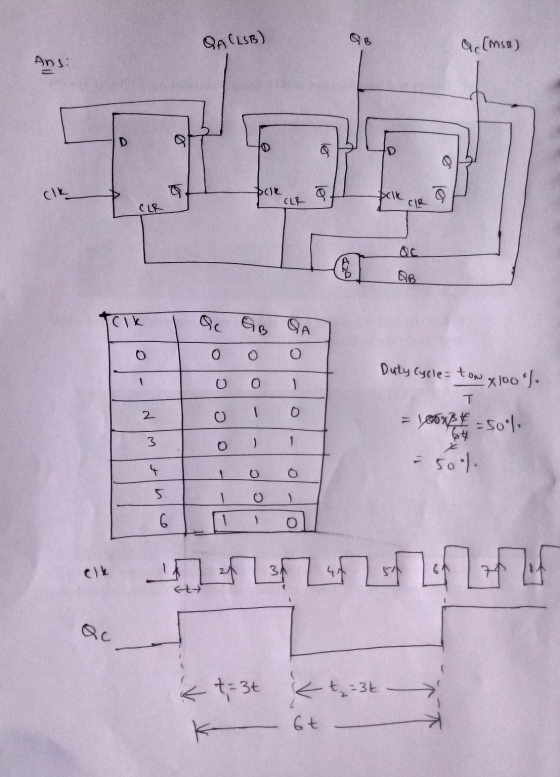
Draw(Design) a frequency divider by 10 circuit only using digital static circuits. but don't use any external RESET(CLEAR) signal to circuits. Circuits must have a one external Input(input clock)....
Draw(Design) a frequency divider by 10 circuit only using digital static circuits. but don't use any external RESET(CLEAR) signal to circuits. Circuits must have a one external Input(input clock). neglect output clock duty ratio, but 50% duty ratio is best. (a) Design using D-flip-flops (b) Design using JK-Flip-flops thanks you.
1. Design a 3 bit sequential circuit using T flip flops and one input X. When...
1. Design a 3 bit sequential circuit using T flip flops and one input X. When X = 0 the state of the circuit remains the same. When X = 1 the circuit goes through state transition from 0 -> 6 -> 2 -> 3 -> 5 -> 0. Make the state table, state equation and state diagram. Need help trying to understand how to set up the truth table, should I use a JK truth table and go on...
Its logic design my sequence is 127605 i need help with all this pages please and thank you
 Its logic design
my sequence is 127605
i need help with all this pages please and thank you
27 60 Experiment 4 Six-State Up-Down Counter 1 Objective To become familiar with the design procedures of a counter, which are applicable to the design of other synchronous sequential circuits. 2 Problem description A six-state up-down counter is to be designed. Three flip-flops with outputs Q2,Qi and Qo are required in the design. As shown in Figure 1, the counter is initialized...
Its logic design
my sequence is 127605
i need help with all this pages please and thank you
27 60 Experiment 4 Six-State Up-Down Counter 1 Objective To become familiar with the design procedures of a counter, which are applicable to the design of other synchronous sequential circuits. 2 Problem description A six-state up-down counter is to be designed. Three flip-flops with outputs Q2,Qi and Qo are required in the design. As shown in Figure 1, the counter is initialized...
Please send an easy to read circuit design as well and explain how it works. 4:02...
 Please send an easy to read circuit design as well and explain
how it works.
4:02 00 LTE il 50% + ENEE 2586 - Lab 9_f... @ + : ENEF 356 Lab -Sequence Detector ENEE 2586 Lab #9 - Sequence Detector Purpose: The goal of this lab is to design a sequence detector using sequential logic circuits Procedure: 1. Design a sequential logic circuit to check an input stream labeled X and to produce an output Z=1 for any input...
Please send an easy to read circuit design as well and explain
how it works.
4:02 00 LTE il 50% + ENEE 2586 - Lab 9_f... @ + : ENEF 356 Lab -Sequence Detector ENEE 2586 Lab #9 - Sequence Detector Purpose: The goal of this lab is to design a sequence detector using sequential logic circuits Procedure: 1. Design a sequential logic circuit to check an input stream labeled X and to produce an output Z=1 for any input...
bilbecome famillar with t Objective design of other smchronos e pieos 2A Problem description six-state up-down...
 bilbecome famillar with t Objective design of other smchronos e pieos 2A Problem description six-state up-down co and Qo are required in the desidesi are rotvpulse to the REETInuo a posal state Se where the normal countet direcion Te the circuit in the initial st the RES hown in Fres flip-opw wi the RESET input is O during KESET Input of the couner th counting sequence is signal Cwa reversed irc- s an up-counter. The RES So 0. Ss S4...
Can someone please show me a circuit diagram so i can see how to construct this...
 Can someone please show me a circuit diagram so i can see how to
construct this on a bread board i am id 6 yhanks in advance
EEET-2251: Course & Projoct Guide 2018 EEET-2251: Cousc &Projoct Guide 2018 affic Light Controller A single switch must set your HC74 based state machine to the initial state (the U state This lab will get you to design a simple controller for a pedestrian crossing based on synchronous digital logic. You will master...
Can someone please show me a circuit diagram so i can see how to
construct this on a bread board i am id 6 yhanks in advance
EEET-2251: Course & Projoct Guide 2018 EEET-2251: Cousc &Projoct Guide 2018 affic Light Controller A single switch must set your HC74 based state machine to the initial state (the U state This lab will get you to design a simple controller for a pedestrian crossing based on synchronous digital logic. You will master...
In this lab, you will design a finite state machine to control the tail lights of...
 In this lab, you will design a finite state machine to control the tail lights of an unsual car. There are three lights on each side that operate in sequence to indicate thedirection of a turn. Figure ! shows the tail lights and Figure 2 shows the flashing sequence for (a) left turns and (b) right rums. ZOTTAS Figure 28:8: BCECECece BCECECECes BCECECECB BCECECBCB 8888 Figure 2 Part 1 - FSM Design Start with designing the state transition diagram for...
 Its logic design
my sequence is 127605
i need help with all this pages please and thank you
27 60 Experiment 4 Six-State Up-Down Counter 1 Objective To become familiar with the design procedures of a counter, which are applicable to the design of other synchronous sequential circuits. 2 Problem description A six-state up-down counter is to be designed. Three flip-flops with outputs Q2,Qi and Qo are required in the design. As shown in Figure 1, the counter is initialized...
Its logic design
my sequence is 127605
i need help with all this pages please and thank you
27 60 Experiment 4 Six-State Up-Down Counter 1 Objective To become familiar with the design procedures of a counter, which are applicable to the design of other synchronous sequential circuits. 2 Problem description A six-state up-down counter is to be designed. Three flip-flops with outputs Q2,Qi and Qo are required in the design. As shown in Figure 1, the counter is initialized...
 Please send an easy to read circuit design as well and explain
how it works.
4:02 00 LTE il 50% + ENEE 2586 - Lab 9_f... @ + : ENEF 356 Lab -Sequence Detector ENEE 2586 Lab #9 - Sequence Detector Purpose: The goal of this lab is to design a sequence detector using sequential logic circuits Procedure: 1. Design a sequential logic circuit to check an input stream labeled X and to produce an output Z=1 for any input...
Please send an easy to read circuit design as well and explain
how it works.
4:02 00 LTE il 50% + ENEE 2586 - Lab 9_f... @ + : ENEF 356 Lab -Sequence Detector ENEE 2586 Lab #9 - Sequence Detector Purpose: The goal of this lab is to design a sequence detector using sequential logic circuits Procedure: 1. Design a sequential logic circuit to check an input stream labeled X and to produce an output Z=1 for any input...
 bilbecome famillar with t Objective design of other smchronos e pieos 2A Problem description six-state up-down co and Qo are required in the desidesi are rotvpulse to the REETInuo a posal state Se where the normal countet direcion Te the circuit in the initial st the RES hown in Fres flip-opw wi the RESET input is O during KESET Input of the couner th counting sequence is signal Cwa reversed irc- s an up-counter. The RES So 0. Ss S4...
 Can someone please show me a circuit diagram so i can see how to
construct this on a bread board i am id 6 yhanks in advance
EEET-2251: Course & Projoct Guide 2018 EEET-2251: Cousc &Projoct Guide 2018 affic Light Controller A single switch must set your HC74 based state machine to the initial state (the U state This lab will get you to design a simple controller for a pedestrian crossing based on synchronous digital logic. You will master...
Can someone please show me a circuit diagram so i can see how to
construct this on a bread board i am id 6 yhanks in advance
EEET-2251: Course & Projoct Guide 2018 EEET-2251: Cousc &Projoct Guide 2018 affic Light Controller A single switch must set your HC74 based state machine to the initial state (the U state This lab will get you to design a simple controller for a pedestrian crossing based on synchronous digital logic. You will master...
 In this lab, you will design a finite state machine to control the tail lights of an unsual car. There are three lights on each side that operate in sequence to indicate thedirection of a turn. Figure ! shows the tail lights and Figure 2 shows the flashing sequence for (a) left turns and (b) right rums. ZOTTAS Figure 28:8: BCECECece BCECECECes BCECECECB BCECECBCB 8888 Figure 2 Part 1 - FSM Design Start with designing the state transition diagram for...
Most questions answered within 3 hours.
-
By 2025, annual consumption in emerging markets will total $30
trillion and contribute more than ________...
asked 4 minutes ago -
At what point does reformation cease to be a viable option for
those who are oppressed...
asked 8 minutes ago -
When rolling a die 129 times, what is the probability of rolling
a 6 no more...
asked 6 minutes ago -
Place letters corresponding to amounts in the proper order for
lightest to heaviest samples:
a) 2100...
asked 12 minutes ago -
Consider the multicore processor with 6 heterogeneous cores
labelled C1, C2, C3, C4, C5, and C6....
asked 14 minutes ago -
Document system components according to standards and procedures
(Implement and hand over system components) IT administrative
asked 15 minutes ago -
The college asked 700 students if they wanted a longer spring
break and 600 students said...
asked 14 minutes ago -
Determine the temperature (in Celsius) at which 1.00 mole of an
ideal gas will have a...
asked 39 minutes ago -
Japan’s combination of X and Y
Canada’s combination of X and Y
100x and 0y
50x...
asked 31 minutes ago -
[1] Household statistics include individuals living alone or in
groups in:
A) apartments.
B) military barracks....
asked 42 minutes ago -
What is the % w/v when 80 mL of a 2.0% solution is mixed with 50...
asked 46 minutes ago -
How can I solve the following using a TI83
Claim: Most adults would erase all of...
asked 58 minutes ago