
Homework Answers
Add Answer to:
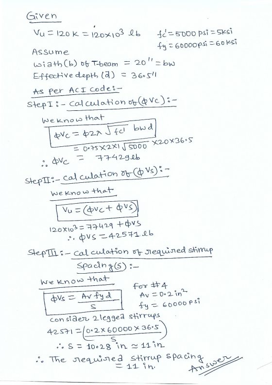
Problem 4 If the factored shear demand on the T-Beam, Vu, is 120k, calculate the required...
A section for a NWC beam is shown below. Your task is to work on the...
 A section for a NWC beam is shown below. Your task is to work on the shear design of this beam. Assume fc=4000psi; fy=60ksi. Use No 3 Grade double-leg stirrup, yield strength of stirrups=fys = 60 ksi. in. stirrups 21 in. 12 in 4) Assuming low shear stresses, (i.e., Vs<41fc bw d), the maximum stirrup spacing based on beam depth is: A. 24 -in B. 12.5-in C. 6.25-in D. 12-in 5) If Vc = 37.9 kip and Vu= 73 kip,...
3. Using the same T-beam from Problem 2, complete each of the following: Calculate the shear...
 3. Using the same T-beam from Problem 2, complete each of the following: Calculate the shear strength of the concrete, Ve, using the equation for membens subjected to shear and flexure only. (10) IfVarcq-,-60 kips, calculate the MAXIMUM permissible spacing of #4 single leg stirrups based on strength and geometry. (10) Check Vs(max). (10) a. b. c. re-5000 psi fy-60 ksi 24 in. 3 in. 6 in. 28 in. 12 in.
(40 pts) The simply supported beam shown in the figure below is being designed for shear. #3 stirrups (Grade 40) are to be used. 2. Wu = 4 kips/ft (includes self weight) wDL-1 kips/ft, wu...
 (40 pts) The simply supported beam shown in the figure below is being designed for shear. #3 stirrups (Grade 40) are to be used. 2. Wu = 4 kips/ft (includes self weight) wDL-1 kips/ft, wu 1.75 kips/ft h= 18" d = 15" L=20ft- fe-4000 psi Yoon- 150 lbf/t E-29,000 ksi fy60 ksi 2 IS Draw the factored shear envelope for Vu c. d. Determine the resistance to shear provided by the concrete. Are there any regions where no shear stirrups...
Problem 2: Design of T-beam Calculate the reinforcing required for the T-beam system below 22 30 ...
 reinforced concrete design
Problem 2: Design of T-beam Calculate the reinforcing required for the T-beam system below 22 30 15 15 10'0 10'0 10 0 1 of 2 live load is 400 lbf/ft2 and use the dimensions shown in the figure. (a) Calculate the maximum factored moment (note: remember to include the self-weight of slab and beams) (b) Determine the effective flange width (c) Check if a
reinforced concrete design
Problem 2: Design of T-beam Calculate the reinforcing required for the T-beam system below 22 30 15 15 10'0 10'0 10 0 1 of 2 live load is 400 lbf/ft2 and use the dimensions shown in the figure. (a) Calculate the maximum factored moment (note: remember to include the self-weight of slab and beams) (b) Determine the effective flange width (c) Check if a
M 3: (20 points) Design the stirrup spacing for the beam shown below. Change your design between ...
 m 3: (20 points) Design the stirrup spacing for the beam shown below. Change your design between Zones 1, 2, and 3 of the beam length, using a uniform spacing in each zone. Ignore the self-weight of the beam. Loads on the beam are service loads so load factors must be applied according to ACI 318 (subscripts "d" and T" denote dead and live loads, respectively). Material strengths are fe 4,0oo psi and fy 60,000 psi. The total factored shear...
Problem 2 (25 points) A rectangular reinforced concrete beam has a width b-15 inches and effecti...
 Problem 2 (25 points) A rectangular reinforced concrete beam has a width b-15 inches and effecti Concrete com ve depth d-24 inches. orcement fy- 60 ksi. imate load - 6 k/R pressive strength fe -4,000 psi and yield stress of steel reinf The beam is simply supported and subjected to a uniformly distributed ulti that includes the weight of the beam. Span is 28 feet. Assume interior exposure. s and show the proposed shear reinforcement Design the beam for shear...
Problem 1. (40 pts) Here is a design for a beam as shown in Figs Check...
 Problem 1. (40 pts) Here is a design for a beam as shown in Figs Check if this section can resist the following loading conditions in the beam according to ACI-318. Use fc -4000 psi and fy - 60,000 psi. Assume that the clear cover is 1.5" (typical) for all and the vertical spacing between #8 bars is 1 inch. Both End (L Center (L2) #8 bars #8 Stirrup #3@ 8" 8#8 bars 20 in Stirrup: 6# 8 bars Pu=15...
Concrete design Problem #2: Determine the appropriate shear reinforcement required for the beam shown (spacing of...
 Concrete design
Problem #2: Determine the appropriate shear reinforcement required for the beam shown (spacing of stirrups). Do not consider different loading cases for live loads and the dead load shown includes the beam's weight. Assumere 4000 psi, fy-60000 psi, and use # 3 U-shaped stirrups Note: Divide the beam into segments, 36" each where appropriate. 20k () 30k(L) 0-4 255 sy 5 #10
Concrete design
Problem #2: Determine the appropriate shear reinforcement required for the beam shown (spacing of stirrups). Do not consider different loading cases for live loads and the dead load shown includes the beam's weight. Assumere 4000 psi, fy-60000 psi, and use # 3 U-shaped stirrups Note: Divide the beam into segments, 36" each where appropriate. 20k () 30k(L) 0-4 255 sy 5 #10
4. Determine the flexural strength (фМп) and shear strength (OVn) of the given section below. The RC beam in Engineering Building is reinforced with 4#10 for tensile reinforcement at the bottom,...
 4. Determine the flexural strength (фМп) and shear strength (OVn) of the given section below. The RC beam in Engineering Building is reinforced with 4#10 for tensile reinforcement at the bottom, 2#4 for compressive reinforcement at the top, and stirrups with #3@ 9" on center. (fc 6 ksi, fy 60 ksi for top and bottom reinforcement, and fyt -40 ksi for stirrups): Case 1: t- 3 in (20 points) and Case 2: t- 10 in (20 points) . 14" 6...
Course work problem 3: Designing of the steel beam To design low carbon rolled steel double T-cross-section beam. For this purpose must be fulfilled: 1. Calculate the shear forces and bending moments...
 Course work problem 3: Designing of the steel beam
To design low carbon rolled steel double T-cross-section beam.
For this purpose must be fulfilled:
1. Calculate the shear forces and bending moments Qy and Mx
diagrams.
2. Selecting rolled steel in the form of a double T-
cross-section standard number from strength condition
3. Calculate the shear stresses in the critical points of
cross-section
4. Check the condition of strength points with combined stress
state
5. Determine the deflection and...
Course work problem 3: Designing of the steel beam
To design low carbon rolled steel double T-cross-section beam.
For this purpose must be fulfilled:
1. Calculate the shear forces and bending moments Qy and Mx
diagrams.
2. Selecting rolled steel in the form of a double T-
cross-section standard number from strength condition
3. Calculate the shear stresses in the critical points of
cross-section
4. Check the condition of strength points with combined stress
state
5. Determine the deflection and...
 A section for a NWC beam is shown below. Your task is to work on the shear design of this beam. Assume fc=4000psi; fy=60ksi. Use No 3 Grade double-leg stirrup, yield strength of stirrups=fys = 60 ksi. in. stirrups 21 in. 12 in 4) Assuming low shear stresses, (i.e., Vs<41fc bw d), the maximum stirrup spacing based on beam depth is: A. 24 -in B. 12.5-in C. 6.25-in D. 12-in 5) If Vc = 37.9 kip and Vu= 73 kip,...
 3. Using the same T-beam from Problem 2, complete each of the following: Calculate the shear strength of the concrete, Ve, using the equation for membens subjected to shear and flexure only. (10) IfVarcq-,-60 kips, calculate the MAXIMUM permissible spacing of #4 single leg stirrups based on strength and geometry. (10) Check Vs(max). (10) a. b. c. re-5000 psi fy-60 ksi 24 in. 3 in. 6 in. 28 in. 12 in.
 (40 pts) The simply supported beam shown in the figure below is being designed for shear. #3 stirrups (Grade 40) are to be used. 2. Wu = 4 kips/ft (includes self weight) wDL-1 kips/ft, wu 1.75 kips/ft h= 18" d = 15" L=20ft- fe-4000 psi Yoon- 150 lbf/t E-29,000 ksi fy60 ksi 2 IS Draw the factored shear envelope for Vu c. d. Determine the resistance to shear provided by the concrete. Are there any regions where no shear stirrups...
 reinforced concrete design
Problem 2: Design of T-beam Calculate the reinforcing required for the T-beam system below 22 30 15 15 10'0 10'0 10 0 1 of 2 live load is 400 lbf/ft2 and use the dimensions shown in the figure. (a) Calculate the maximum factored moment (note: remember to include the self-weight of slab and beams) (b) Determine the effective flange width (c) Check if a
reinforced concrete design
Problem 2: Design of T-beam Calculate the reinforcing required for the T-beam system below 22 30 15 15 10'0 10'0 10 0 1 of 2 live load is 400 lbf/ft2 and use the dimensions shown in the figure. (a) Calculate the maximum factored moment (note: remember to include the self-weight of slab and beams) (b) Determine the effective flange width (c) Check if a
 m 3: (20 points) Design the stirrup spacing for the beam shown below. Change your design between Zones 1, 2, and 3 of the beam length, using a uniform spacing in each zone. Ignore the self-weight of the beam. Loads on the beam are service loads so load factors must be applied according to ACI 318 (subscripts "d" and T" denote dead and live loads, respectively). Material strengths are fe 4,0oo psi and fy 60,000 psi. The total factored shear...
 Problem 2 (25 points) A rectangular reinforced concrete beam has a width b-15 inches and effecti Concrete com ve depth d-24 inches. orcement fy- 60 ksi. imate load - 6 k/R pressive strength fe -4,000 psi and yield stress of steel reinf The beam is simply supported and subjected to a uniformly distributed ulti that includes the weight of the beam. Span is 28 feet. Assume interior exposure. s and show the proposed shear reinforcement Design the beam for shear...
 Problem 1. (40 pts) Here is a design for a beam as shown in Figs Check if this section can resist the following loading conditions in the beam according to ACI-318. Use fc -4000 psi and fy - 60,000 psi. Assume that the clear cover is 1.5" (typical) for all and the vertical spacing between #8 bars is 1 inch. Both End (L Center (L2) #8 bars #8 Stirrup #3@ 8" 8#8 bars 20 in Stirrup: 6# 8 bars Pu=15...
 Concrete design
Problem #2: Determine the appropriate shear reinforcement required for the beam shown (spacing of stirrups). Do not consider different loading cases for live loads and the dead load shown includes the beam's weight. Assumere 4000 psi, fy-60000 psi, and use # 3 U-shaped stirrups Note: Divide the beam into segments, 36" each where appropriate. 20k () 30k(L) 0-4 255 sy 5 #10
Concrete design
Problem #2: Determine the appropriate shear reinforcement required for the beam shown (spacing of stirrups). Do not consider different loading cases for live loads and the dead load shown includes the beam's weight. Assumere 4000 psi, fy-60000 psi, and use # 3 U-shaped stirrups Note: Divide the beam into segments, 36" each where appropriate. 20k () 30k(L) 0-4 255 sy 5 #10
 4. Determine the flexural strength (фМп) and shear strength (OVn) of the given section below. The RC beam in Engineering Building is reinforced with 4#10 for tensile reinforcement at the bottom, 2#4 for compressive reinforcement at the top, and stirrups with #3@ 9" on center. (fc 6 ksi, fy 60 ksi for top and bottom reinforcement, and fyt -40 ksi for stirrups): Case 1: t- 3 in (20 points) and Case 2: t- 10 in (20 points) . 14" 6...
 Course work problem 3: Designing of the steel beam
To design low carbon rolled steel double T-cross-section beam.
For this purpose must be fulfilled:
1. Calculate the shear forces and bending moments Qy and Mx
diagrams.
2. Selecting rolled steel in the form of a double T-
cross-section standard number from strength condition
3. Calculate the shear stresses in the critical points of
cross-section
4. Check the condition of strength points with combined stress
state
5. Determine the deflection and...
Course work problem 3: Designing of the steel beam
To design low carbon rolled steel double T-cross-section beam.
For this purpose must be fulfilled:
1. Calculate the shear forces and bending moments Qy and Mx
diagrams.
2. Selecting rolled steel in the form of a double T-
cross-section standard number from strength condition
3. Calculate the shear stresses in the critical points of
cross-section
4. Check the condition of strength points with combined stress
state
5. Determine the deflection and...
Most questions answered within 3 hours.
-
Computer Programming II CS141(Java)
Mention the appropriate relationship between following
classes:
HOD–StaffMember
Car–Ferrari
Student-Address
BankAccount–FixedAccount
House-Building...
asked 2 hours ago -
Assume one of your finals has 50 questions on it, and
lucky for you, it's all...
asked 3 hours ago -
Rice Products in Bangladesh
Business behavior is derived in large part from the basic cultural
environment...
asked 5 hours ago -
The following base sequence is found for a mRNA fragment from
wild-type E. coli: 5'- UAUCAGUAGAUAAUGUAACC-3'...
asked 5 hours ago -
For this exercise, round all regression parameters to three
decimal places.
One of the two tables...
asked 5 hours ago -
What is the 5% level of significance for mean = 3.60, standard
deviation = 0.94, and...
asked 5 hours ago -
Prior to beginning work on this discussion, please read the
article by Hayley Peterson, 15 Companies...
asked 6 hours ago -
Which pair of aqueous solutions, when mixed, will form a
precipitate?
A) NaNO3 and AgC2H3O2
B)...
asked 6 hours ago -
1-Write an algorithm to get two numbers from the user (as
inputs) and calculate the sum...
asked 9 hours ago -
Define white-collar crime. What is the difference between
offender and offense-based definitions of white-collar crime? What...
asked 10 hours ago -
Consider a reaction which is 1st order with respect to A and 1st
order with respect...
asked 10 hours ago -
c++
The length of the hypotenuse of a right-angled triangle is the
square root of the...
asked 10 hours ago