
Homework Answers
Add Answer to:
6. Given the following closed-loop system, the objective is to design a controller D(s) such that...
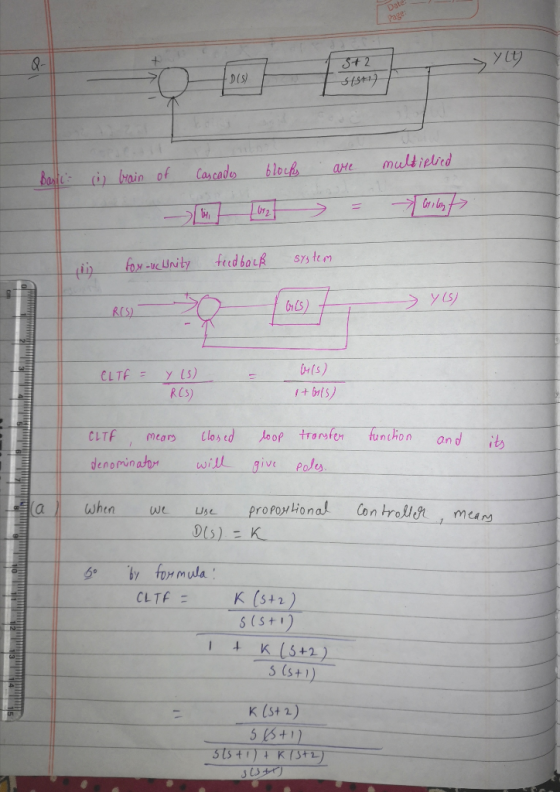
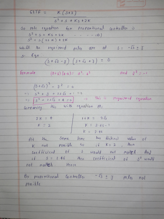
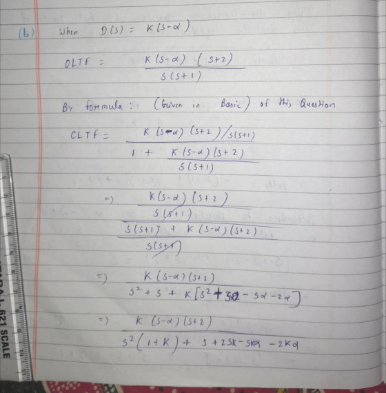
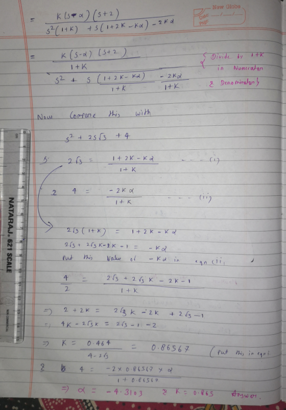
Question 1 (60 points) Consider the following block diagram where G(s)- Controller R(s) G(s) (a) Sketch the root locus assuming a proportional controller is used. [25 points] (b) Design specifica...
 Question 1 (60 points) Consider the following block diagram where G(s)- Controller R(s) G(s) (a) Sketch the root locus assuming a proportional controller is used. [25 points] (b) Design specifications require a closed-loop pole at (-3+j1). Design a lead compensator to make sure the root locus goes through this point. For the design, pick the pole of the compensator at-23 and analytically find its zero. (Hint: Lead compensator transfer function will be Ge (s)$+23 First plot the poles and zeros...
2. Controller Design For each of the following plants G, design a compensator G, so that the closed loop system KG, G (1 + KG, G has two dominant poles near 2 ± i Plot a root locus plot for the s...
 2. Controller Design For each of the following plants G, design a compensator G, so that the closed loop system KG, G (1 + KG, G has two dominant poles near 2 ± i Plot a root locus plot for the system before adding the compensator and another plot for after. Use the simplest G that you can find. Determine the gain K that will achieve the desired poles 142
2. Controller Design For each of the following plants G,...
2. Controller Design For each of the following plants G, design a compensator G, so that the closed loop system KG, G (1 + KG, G has two dominant poles near 2 ± i Plot a root locus plot for the system before adding the compensator and another plot for after. Use the simplest G that you can find. Determine the gain K that will achieve the desired poles 142
2. Controller Design For each of the following plants G,...
1. Consider the following feedback control system Controller Process 1 G(s) R(s) Y(s) $2+5s+6 Below are...
 1. Consider the following feedback control system Controller Process 1 G(s) R(s) Y(s) $2+5s+6 Below are two potential controllers for this system: 1) Ge(s) K (Proportional controller) 2) Ge(s) K(1 1/s) (Proportional-integral controller) The design specifications are t 3.2s and P. 0. 10% for a unit step input (a) Determine the area on the S-plane where the dominant closed loop poles must be located such that the design requirements are satisfied. (b) Sketch the root locus with each of the...
Feedback Control of Dynamic System Please Let me know how to solve this problem (5) For the following unity-feedback control system, Y(s) R(s)E D(s) (s+ 2) we want to design a controller D(s) D(s)+a)...
 Feedback Control of Dynamic System
Please Let me know how to solve this problem
(5) For the following unity-feedback control system, Y(s) R(s)E D(s) (s+ 2) we want to design a controller D(s) D(s)+a) that makes the closed-loop stable for certain positive K values. Design the parameters a and b to satisfy the design condition through the root- locus method
(5) For the following unity-feedback control system, Y(s) R(s)E D(s) (s+ 2) we want to design a controller D(s) D(s)+a)...
Feedback Control of Dynamic System
Please Let me know how to solve this problem
(5) For the following unity-feedback control system, Y(s) R(s)E D(s) (s+ 2) we want to design a controller D(s) D(s)+a) that makes the closed-loop stable for certain positive K values. Design the parameters a and b to satisfy the design condition through the root- locus method
(5) For the following unity-feedback control system, Y(s) R(s)E D(s) (s+ 2) we want to design a controller D(s) D(s)+a)...
b) Design a PID controller via root-locus to satisfy the following requirements for the controlled system...
 b) Design a PID controller via root-locus to satisfy the following requirements for the controlled system 2.9 T,-0.18 The following notation has been used for the system parameters: Percent Overshoot(%)-pos Settling time (s) Peak time (s)- Tp Start by manual calculations for the locations of the poles and zeros of the PID controller to satisfy the requirements. Find the required location of the zero for PD control and introduce PI control. Afterwards, use the Sisotool in MATLAB to simulate the...
D9.2 Design a state-feedback controller for the following systems. Determine the controller gains, open-loop transfer functions,...
 D9.2 Design a state-feedback controller for the following systems. Determine the controller gains, open-loop transfer functions, and closed-loop transfer functions Use the open-loop transfer functions to obtain root locus, Bode plots, and gain and phase margins LU u=-kx + r Closed-loop poles at s --1tj 2
Consider a unity feedback control architecture where P(s) = 1/s^2 and C(s) = K * ((s + z)/(s + p)...
 Consider a unity feedback control architecture where P(s) =
1/s^2 and C(s) = K * ((s + z)/(s + p)) . It is desired to design
the controller to place the dominant closed-loop poles at sd = −2 ±
2j. Fix the pole of the compensator at −20 rad/sec and use root
locus techniques to find values of z and K to place the closed–loop
poles at sd .
Problem 4 (placing a zero) Consider a unity feedback control architecture...
Consider a unity feedback control architecture where P(s) =
1/s^2 and C(s) = K * ((s + z)/(s + p)) . It is desired to design
the controller to place the dominant closed-loop poles at sd = −2 ±
2j. Fix the pole of the compensator at −20 rad/sec and use root
locus techniques to find values of z and K to place the closed–loop
poles at sd .
Problem 4 (placing a zero) Consider a unity feedback control architecture...
Thank You and Thumps Up. For the open loop system shown in the block diagram, sketch...
 Thank You and Thumps Up. For the open loop system shown in the
block diagram, sketch the root-locus for the proportional control.
Design a controller using a pure zero to place the closed-loop
roots in the desired locations shown in the s-plane.
2 5
Thank You and Thumps Up. For the open loop system shown in the
block diagram, sketch the root-locus for the proportional control.
Design a controller using a pure zero to place the closed-loop
roots in the desired locations shown in the s-plane.
2 5
1. [25%] Consider the closed-loop system shown where it is desired to stabilize the system with...
 1. [25%] Consider the closed-loop system shown where it is desired to stabilize the system with feedback where the control law is a form of a PID controller. Design using the Root Locus Method such that the: a. percent overshoot is less than 10% for a unit step b. settling time is less than 4 seconds, c. steady-state absolute error (not percent error) due to a unit ramp input (r=t) is less than 1. d. Note: The actuator u(t) saturates...
Question 1 (60 points) Consider the following block diagram where G (s) Froarss RMs) GIs) Gls) (a) Sketch the root locus assuming a proportional controller is used. (b) Assume design spocifications r...
 Question 1 (60 points) Consider the following block diagram where G (s) Froarss RMs) GIs) Gls) (a) Sketch the root locus assuming a proportional controller is used. (b) Assume design spocifications require a closed-loop pole at (-3+ j1). Design a lead compensator sure the root locus goes through this point. For the design, pick the pole of the compensator at -23 and analytically find its zero location. (c) Sketch the root locus with the lead compensator in place.
Question 1...
Question 1 (60 points) Consider the following block diagram where G (s) Froarss RMs) GIs) Gls) (a) Sketch the root locus assuming a proportional controller is used. (b) Assume design spocifications require a closed-loop pole at (-3+ j1). Design a lead compensator sure the root locus goes through this point. For the design, pick the pole of the compensator at -23 and analytically find its zero location. (c) Sketch the root locus with the lead compensator in place.
Question 1...
 Question 1 (60 points) Consider the following block diagram where G(s)- Controller R(s) G(s) (a) Sketch the root locus assuming a proportional controller is used. [25 points] (b) Design specifications require a closed-loop pole at (-3+j1). Design a lead compensator to make sure the root locus goes through this point. For the design, pick the pole of the compensator at-23 and analytically find its zero. (Hint: Lead compensator transfer function will be Ge (s)$+23 First plot the poles and zeros...
 2. Controller Design For each of the following plants G, design a compensator G, so that the closed loop system KG, G (1 + KG, G has two dominant poles near 2 ± i Plot a root locus plot for the system before adding the compensator and another plot for after. Use the simplest G that you can find. Determine the gain K that will achieve the desired poles 142
2. Controller Design For each of the following plants G,...
2. Controller Design For each of the following plants G, design a compensator G, so that the closed loop system KG, G (1 + KG, G has two dominant poles near 2 ± i Plot a root locus plot for the system before adding the compensator and another plot for after. Use the simplest G that you can find. Determine the gain K that will achieve the desired poles 142
2. Controller Design For each of the following plants G,...
 1. Consider the following feedback control system Controller Process 1 G(s) R(s) Y(s) $2+5s+6 Below are two potential controllers for this system: 1) Ge(s) K (Proportional controller) 2) Ge(s) K(1 1/s) (Proportional-integral controller) The design specifications are t 3.2s and P. 0. 10% for a unit step input (a) Determine the area on the S-plane where the dominant closed loop poles must be located such that the design requirements are satisfied. (b) Sketch the root locus with each of the...
 Feedback Control of Dynamic System
Please Let me know how to solve this problem
(5) For the following unity-feedback control system, Y(s) R(s)E D(s) (s+ 2) we want to design a controller D(s) D(s)+a) that makes the closed-loop stable for certain positive K values. Design the parameters a and b to satisfy the design condition through the root- locus method
(5) For the following unity-feedback control system, Y(s) R(s)E D(s) (s+ 2) we want to design a controller D(s) D(s)+a)...
Feedback Control of Dynamic System
Please Let me know how to solve this problem
(5) For the following unity-feedback control system, Y(s) R(s)E D(s) (s+ 2) we want to design a controller D(s) D(s)+a) that makes the closed-loop stable for certain positive K values. Design the parameters a and b to satisfy the design condition through the root- locus method
(5) For the following unity-feedback control system, Y(s) R(s)E D(s) (s+ 2) we want to design a controller D(s) D(s)+a)...
 b) Design a PID controller via root-locus to satisfy the following requirements for the controlled system 2.9 T,-0.18 The following notation has been used for the system parameters: Percent Overshoot(%)-pos Settling time (s) Peak time (s)- Tp Start by manual calculations for the locations of the poles and zeros of the PID controller to satisfy the requirements. Find the required location of the zero for PD control and introduce PI control. Afterwards, use the Sisotool in MATLAB to simulate the...
 D9.2 Design a state-feedback controller for the following systems. Determine the controller gains, open-loop transfer functions, and closed-loop transfer functions Use the open-loop transfer functions to obtain root locus, Bode plots, and gain and phase margins LU u=-kx + r Closed-loop poles at s --1tj 2
 Consider a unity feedback control architecture where P(s) =
1/s^2 and C(s) = K * ((s + z)/(s + p)) . It is desired to design
the controller to place the dominant closed-loop poles at sd = −2 ±
2j. Fix the pole of the compensator at −20 rad/sec and use root
locus techniques to find values of z and K to place the closed–loop
poles at sd .
Problem 4 (placing a zero) Consider a unity feedback control architecture...
Consider a unity feedback control architecture where P(s) =
1/s^2 and C(s) = K * ((s + z)/(s + p)) . It is desired to design
the controller to place the dominant closed-loop poles at sd = −2 ±
2j. Fix the pole of the compensator at −20 rad/sec and use root
locus techniques to find values of z and K to place the closed–loop
poles at sd .
Problem 4 (placing a zero) Consider a unity feedback control architecture...
 Thank You and Thumps Up. For the open loop system shown in the
block diagram, sketch the root-locus for the proportional control.
Design a controller using a pure zero to place the closed-loop
roots in the desired locations shown in the s-plane.
2 5
Thank You and Thumps Up. For the open loop system shown in the
block diagram, sketch the root-locus for the proportional control.
Design a controller using a pure zero to place the closed-loop
roots in the desired locations shown in the s-plane.
2 5
 1. [25%] Consider the closed-loop system shown where it is desired to stabilize the system with feedback where the control law is a form of a PID controller. Design using the Root Locus Method such that the: a. percent overshoot is less than 10% for a unit step b. settling time is less than 4 seconds, c. steady-state absolute error (not percent error) due to a unit ramp input (r=t) is less than 1. d. Note: The actuator u(t) saturates...
 Question 1 (60 points) Consider the following block diagram where G (s) Froarss RMs) GIs) Gls) (a) Sketch the root locus assuming a proportional controller is used. (b) Assume design spocifications require a closed-loop pole at (-3+ j1). Design a lead compensator sure the root locus goes through this point. For the design, pick the pole of the compensator at -23 and analytically find its zero location. (c) Sketch the root locus with the lead compensator in place.
Question 1...
Question 1 (60 points) Consider the following block diagram where G (s) Froarss RMs) GIs) Gls) (a) Sketch the root locus assuming a proportional controller is used. (b) Assume design spocifications require a closed-loop pole at (-3+ j1). Design a lead compensator sure the root locus goes through this point. For the design, pick the pole of the compensator at -23 and analytically find its zero location. (c) Sketch the root locus with the lead compensator in place.
Question 1...
Most questions answered within 3 hours.
-
A sock stuck to the side of a clothes-dryer barrel has a
centripetal acceleration of 24...
asked 30 minutes ago -
A perfect gas undergoes an isentropic process such that its
volume doubles. If the ratio of...
asked 50 minutes ago -
list the elements in groups 3A to 6A in the same order as in the
periodic...
asked 59 minutes ago -
Estimating effect size. Peng and Chen (2014)
evaluated effect size estimates for various tests. In their...
asked 1 hour ago -
Write a script in MySQL that creates and calls a stored
procedure name test. This procedure...
asked 1 hour ago -
If we test the following: H0: μ = 17
vs. H1: μ ≠ 17 and the...
asked 1 hour ago -
in the past year TVG had revenues of 3 million, cost
of goods sold of $25...
asked 1 hour ago -
4) In a polypeptide, which bond cannot rotate because of its
partial double bond character?
The...
asked 1 hour ago -
Assume that in the short run L = 1,000 and K = 100. 1. What is...
asked 1 hour ago -
At a given temperature, 2.06 atm of H2 and 3.7 atm of Br2 are
mixed and...
asked 1 hour ago -
Sodium reacts with Hydrochloric acid to form sodium chloride and
hydrogen gas. 2Na(s)+ 2 HCl(aq)-> 2...
asked 1 hour ago -
The following circuits (1 & 2) are combined to form a
series-parallel circuit and resulting circuit...
asked 2 hours ago