
Homework Answers
when b = 4,
the denominator of the plant is given by
(s+1)*(s+2)*(s+4) = s^3 + 7 s^2 + 14 s + 8
The denominator polynomial coefficients = [1 7 14 8]
The simulink model with PI controller is given below

The PI controller block is given below.
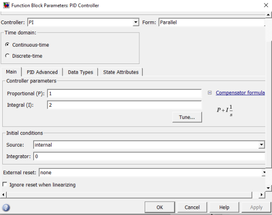
For faster response with no overshoot, you need to tune the controller by clicking on the tune button.
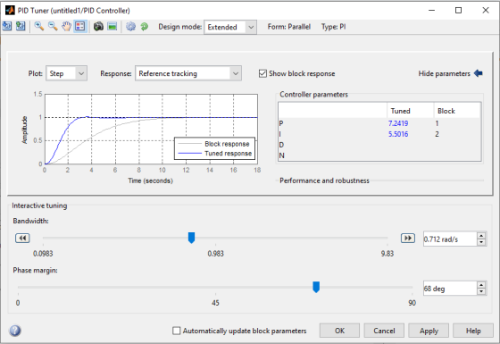
By tuning the controller for best response with no overshoot , the PI gains turn out to be
Kp = 7.2419 and
Ki = 5.5016
With the new designed controller gains, the PI block is given below.

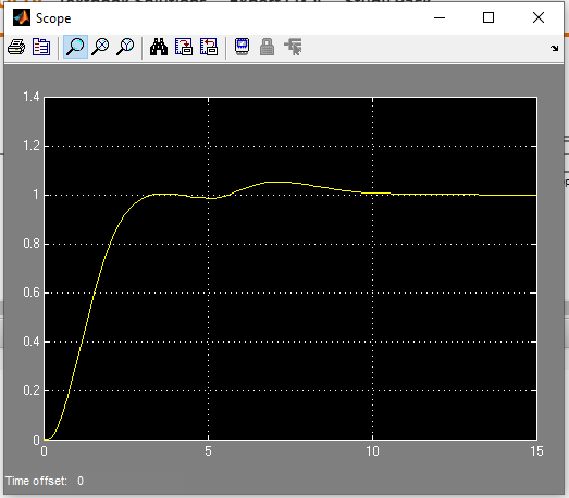
Question b:
The unit step response is given below.
![Scope ] X y 1.4 1.2 1 0.8 0.6 0.4 0.2 0 0 1 2 3 4 5 6 7 8 10 Time offset: 0](http://img.homeworklib.com/questions/f071ac70-b19a-11eb-8804-77a3c69d837b.png?x-oss-process=image/resize,w_560)
Question c:
MATLAB code to obtain the stability of the system
clc;
close all;
clear all;
% define the laplce variable s
s = tf('s');
% define the gains
Kp = 7.2419;
Ki = 5.5016;
% define the controller
Gc = Kp+Ki/s;
% define Gp
Gp = 1/((s+1)*(s+2)*(s+4));
% obtain the closed loop pole locations
figure;
pole(feedback(Gc*Gp,1))
The poles of the system are located at
ans =
-4.6330
-0.8822 + 1.0918i
-0.8822 - 1.0918i
-0.6027
It is observed that the closed loop poles are located on the left side of jw axis. Therefore the system is going to be stable.
Question d: Disturbance rejection analysis
The simulink block diagram is given below.

The response is plotted below.

It is observed that PI control system has rejected the step disturbance and helped track the reference of unity.
when b = 4,
the denominator of the plant is given by
(s+1)*(s+2)*(s+4) = s^3 + 7 s^2 + 14 s + 8
The denominator polynomial coefficients = [1 7 14 8]
The simulink model with PI controller is given below

The PI controller block is given below.

For faster response with no overshoot, you need to tune the controller by clicking on the tune button.

By tuning the controller for best response with no overshoot , the PI gains turn out to be
Kp = 7.2419 and
Ki = 5.5016
With the new designed controller gains, the PI block is given below.

Question b:
The unit step response is given below.
![Scope ] X y 1.4 1.2 1 0.8 0.6 0.4 0.2 0 0 1 2 3 4 5 6 7 8 10 Time offset: 0](http://img.homeworklib.com/questions/e2db3b90-b1b0-11eb-9046-3b7ba3c88904.png?x-oss-process=image/resize,w_560)
Question c:
MATLAB code to obtain the stability of the system
clc;
close all;
clear all;
% define the laplce variable s
s = tf('s');
% define the gains
Kp = 7.2419;
Ki = 5.5016;
% define the controller
Gc = Kp+Ki/s;
% define Gp
Gp = 1/((s+1)*(s+2)*(s+4));
% obtain the closed loop pole locations
figure;
pole(feedback(Gc*Gp,1))
The poles of the system are located at
ans =
-4.6330
-0.8822 + 1.0918i
-0.8822 - 1.0918i
-0.6027
It is observed that the closed loop poles are located on the left side of jw axis. Therefore the system is going to be stable.
Question d: Disturbance rejection analysis
The simulink block diagram is given below.

The response is plotted below.
It is observed that PI control system has rejected the step disturbance and helped track the reference of unity.
Add Answer to:
solving using MATLAB When b=4
R X *-9 40) 101G+ ba? exo tima G (S) 1...
please solve as matlab code. The system in Figure 3 comprises a motor and a contoller. The performance requirements entail a steady state error for ramp input r(t) Ct, smaller than 0.01C. Here, C...
 please solve as matlab code.
The system in Figure 3 comprises a motor and a contoller. The performance requirements entail a steady state error for ramp input r(t) Ct, smaller than 0.01C. Here, C is a constant. The overshoot for step input must be such that P.0. 5% and the settling time with a 2% error should be T, 2 seconds (a) Based on rlocus function, write a piece of MATLAB code which establishes the controller. (b) Create the graph...
please solve as matlab code.
The system in Figure 3 comprises a motor and a contoller. The performance requirements entail a steady state error for ramp input r(t) Ct, smaller than 0.01C. Here, C is a constant. The overshoot for step input must be such that P.0. 5% and the settling time with a 2% error should be T, 2 seconds (a) Based on rlocus function, write a piece of MATLAB code which establishes the controller. (b) Create the graph...
PLEASE SOLVE IN MATLAB !!!!!! PLEASE SOLVE IN MATLAB !!!!!! PLEASE SOLVE IN MATLAB !!!!!! PLEASE SOLVE IN MATLAB !!!!!! PLEASE SOLVE IN MATLAB !!!!!! PLEASE SOLVE IN MATLAB !!!!!! PLEASE SOLVE IN MAT...
 PLEASE SOLVE IN MATLAB !!!!!! PLEASE SOLVE IN MATLAB !!!!!!
 PLEASE
SOLVE IN MATLAB !!!!!! PLEASE SOLVE IN MATLAB !!!!!! PLEASE SOLVE
IN MATLAB !!!!!! PLEASE SOLVE IN MATLAB !!!!!! PLEASE SOLVE IN
MATLAB !!!!!!
PROBLEM 3 The system in Figure 3 comprises a motor and a contoller. The performance requirements entail a steady state error for ramp input r(t)-Ct, smaller than 0.01C. Here, C is a constant. The overshoot...
PLEASE SOLVE IN MATLAB !!!!!! PLEASE SOLVE IN MATLAB !!!!!!
PLEASE SOLVE IN MATLAB !!!!!! PLEASE SOLVE IN MATLAB !!!!!! PLEASE
SOLVE IN MATLAB !!!!!! PLEASE SOLVE IN MATLAB !!!!!! PLEASE SOLVE
IN MATLAB !!!!!! PLEASE SOLVE IN MATLAB !!!!!! PLEASE SOLVE IN
MATLAB !!!!!!
PROBLEM 3 The system in Figure 3 comprises a motor and a contoller. The performance requirements entail a steady state error for ramp input r(t)-Ct, smaller than 0.01C. Here, C is a constant. The overshoot...
Write as MATLAB code with comments thank you. The system in Figure 3 comprises a motor and a contoller. The performance requirements entail a steady state error for ramp input r(t) Ct, smaller than 0...
 Write as MATLAB code with comments thank you.
The system in Figure 3 comprises a motor and a contoller. The performance requirements entail a steady state error for ramp input r(t) Ct, smaller than 0.01C. Here, C is a constant. The overshoot for step input must be such that P.0.S 5% and the settling time with a 2% error should be T. 2 seconds. (a) Based on rlocus function, write a piece of MATLAB code which establishes the controller. (b)...
Write as MATLAB code with comments thank you.
The system in Figure 3 comprises a motor and a contoller. The performance requirements entail a steady state error for ramp input r(t) Ct, smaller than 0.01C. Here, C is a constant. The overshoot for step input must be such that P.0.S 5% and the settling time with a 2% error should be T. 2 seconds. (a) Based on rlocus function, write a piece of MATLAB code which establishes the controller. (b)...
1. Consider the following feedback control system Controller Process 1 G(s) R(s) Y(s) $2+5s+6 Below are...
 1. Consider the following feedback control system Controller Process 1 G(s) R(s) Y(s) $2+5s+6 Below are two potential controllers for this system: 1) Ge(s) K (Proportional controller) 2) Ge(s) K(1 1/s) (Proportional-integral controller) The design specifications are t 3.2s and P. 0. 10% for a unit step input (a) Determine the area on the S-plane where the dominant closed loop poles must be located such that the design requirements are satisfied. (b) Sketch the root locus with each of the...
Consider the following closed-loop system: ID(S) Cis) P(s) R(s) — 0 40 52 + 20s +...
 Consider the following closed-loop system: ID(S) Cis) P(s) R(s) — 0 40 52 + 20s + Recall that E(s) = R(s) - Y(s). a) What is steady-state error, ess, in response to a unit step at disturbance input D(s) when a = 12? b) What is steady-state error, ess, in response to a unit step at disturbance input D(s) when a = 12.3? c) What is the fractional change in a between parts (a) and (b)? In other words, what...
Please code on MATLAB and explain D) only. Thank you The block diagram of a linear...
 Please code on MATLAB and explain D) only. Thank you
The block diagram of a linear control system is shown in the Fig., where r(t) is the reference input and n(t) is the disturbance. (a) Find the steady-state value of e(t) when n(t) = 0 and r(t) tuz(t). Find the conditions on the values of a and K so that the solution is valid. N(s) R(S) E(S) S + a K(s + 3) Y(s) S (5² - 1) Controller Process...
Please code on MATLAB and explain D) only. Thank you
The block diagram of a linear control system is shown in the Fig., where r(t) is the reference input and n(t) is the disturbance. (a) Find the steady-state value of e(t) when n(t) = 0 and r(t) tuz(t). Find the conditions on the values of a and K so that the solution is valid. N(s) R(S) E(S) S + a K(s + 3) Y(s) S (5² - 1) Controller Process...
[7] Sketch the root locus for the unity feedback system whose open loop transfer function is K G(s) Draw the root lo...
 [7] Sketch the root locus for the unity feedback system whose open loop transfer function is K G(s) Draw the root locus of the system with the gain Kas a variable. s(s+4) (s2+4s+20) Determine asymptotes, centroid, breakaway point, angle of departure, and the gain at which root locus crosses ja-axis. A control system with type-0 process and a PID controller is shown below. Design the [8 parameters of the PID controller so that the following specifications are satisfied. =100 a)...
R(S) C(s) G(s) Figure P3 G(S) K(s2 – 2s + 2) s(s + 1)(8 +2) Problem...
 R(S) C(s) G(s) Figure P3 G(S) K(s2 – 2s + 2) s(s + 1)(8 +2) Problem 4) (25 points) Consider the same unity feedback control system given in Figure P3 and do the following: a. Determine the system type (type 0, type 1, type 2, etc.) and justify it. (05 points) b. Suppose that 10% maximum overshoot is required as a transient response specification. Find the steady-state error for this P-controlled system, where K = 0.24 for a unit step...
G(S) = 10/[s(s + 1)] R(S) + G(s) Y(S) Ks + 1 a. Let k =...
 G(S) = 10/[s(s + 1)] R(S) + G(s) Y(S) Ks + 1 a. Let k = 0, and determine the percent overshoot and four time constant settling time in the response to a unit step input. b. Determine the value of gain k that will reduce the percent overshoot to 10%, and the corresponding four time constant settling time.
PROBLEM 4 Suppose that a system is shown in Figure 4. There are three controllers that might be incorporated into this system. 1. Ge (s)-K (proportional (P) controller) 2. GS)K/s (integral (I) contro...
 PROBLEM 4 Suppose that a system is shown in Figure 4. There are three controllers that might be incorporated into this system. 1. Ge (s)-K (proportional (P) controller) 2. GS)K/s (integral (I) controller) 3. G (s)K(1+1/s) (proportional, integral (PI) controller) The system requirements are T, < 10 seconds and P0 10% for a unit step response. (a) For the (P) controller, write a piece of MATLAB code to plot root locus for 0<K<,and find the K value so that the...
 please solve as matlab code.
The system in Figure 3 comprises a motor and a contoller. The performance requirements entail a steady state error for ramp input r(t) Ct, smaller than 0.01C. Here, C is a constant. The overshoot for step input must be such that P.0. 5% and the settling time with a 2% error should be T, 2 seconds (a) Based on rlocus function, write a piece of MATLAB code which establishes the controller. (b) Create the graph...
please solve as matlab code.
The system in Figure 3 comprises a motor and a contoller. The performance requirements entail a steady state error for ramp input r(t) Ct, smaller than 0.01C. Here, C is a constant. The overshoot for step input must be such that P.0. 5% and the settling time with a 2% error should be T, 2 seconds (a) Based on rlocus function, write a piece of MATLAB code which establishes the controller. (b) Create the graph...
 PLEASE SOLVE IN MATLAB !!!!!! PLEASE SOLVE IN MATLAB !!!!!!
 PLEASE
SOLVE IN MATLAB !!!!!! PLEASE SOLVE IN MATLAB !!!!!! PLEASE SOLVE
IN MATLAB !!!!!! PLEASE SOLVE IN MATLAB !!!!!! PLEASE SOLVE IN
MATLAB !!!!!!
PROBLEM 3 The system in Figure 3 comprises a motor and a contoller. The performance requirements entail a steady state error for ramp input r(t)-Ct, smaller than 0.01C. Here, C is a constant. The overshoot...
PLEASE SOLVE IN MATLAB !!!!!! PLEASE SOLVE IN MATLAB !!!!!!
PLEASE SOLVE IN MATLAB !!!!!! PLEASE SOLVE IN MATLAB !!!!!! PLEASE
SOLVE IN MATLAB !!!!!! PLEASE SOLVE IN MATLAB !!!!!! PLEASE SOLVE
IN MATLAB !!!!!! PLEASE SOLVE IN MATLAB !!!!!! PLEASE SOLVE IN
MATLAB !!!!!!
PROBLEM 3 The system in Figure 3 comprises a motor and a contoller. The performance requirements entail a steady state error for ramp input r(t)-Ct, smaller than 0.01C. Here, C is a constant. The overshoot...
 Write as MATLAB code with comments thank you.
The system in Figure 3 comprises a motor and a contoller. The performance requirements entail a steady state error for ramp input r(t) Ct, smaller than 0.01C. Here, C is a constant. The overshoot for step input must be such that P.0.S 5% and the settling time with a 2% error should be T. 2 seconds. (a) Based on rlocus function, write a piece of MATLAB code which establishes the controller. (b)...
Write as MATLAB code with comments thank you.
The system in Figure 3 comprises a motor and a contoller. The performance requirements entail a steady state error for ramp input r(t) Ct, smaller than 0.01C. Here, C is a constant. The overshoot for step input must be such that P.0.S 5% and the settling time with a 2% error should be T. 2 seconds. (a) Based on rlocus function, write a piece of MATLAB code which establishes the controller. (b)...
 1. Consider the following feedback control system Controller Process 1 G(s) R(s) Y(s) $2+5s+6 Below are two potential controllers for this system: 1) Ge(s) K (Proportional controller) 2) Ge(s) K(1 1/s) (Proportional-integral controller) The design specifications are t 3.2s and P. 0. 10% for a unit step input (a) Determine the area on the S-plane where the dominant closed loop poles must be located such that the design requirements are satisfied. (b) Sketch the root locus with each of the...
 Consider the following closed-loop system: ID(S) Cis) P(s) R(s) — 0 40 52 + 20s + Recall that E(s) = R(s) - Y(s). a) What is steady-state error, ess, in response to a unit step at disturbance input D(s) when a = 12? b) What is steady-state error, ess, in response to a unit step at disturbance input D(s) when a = 12.3? c) What is the fractional change in a between parts (a) and (b)? In other words, what...
 Please code on MATLAB and explain D) only. Thank you
The block diagram of a linear control system is shown in the Fig., where r(t) is the reference input and n(t) is the disturbance. (a) Find the steady-state value of e(t) when n(t) = 0 and r(t) tuz(t). Find the conditions on the values of a and K so that the solution is valid. N(s) R(S) E(S) S + a K(s + 3) Y(s) S (5² - 1) Controller Process...
Please code on MATLAB and explain D) only. Thank you
The block diagram of a linear control system is shown in the Fig., where r(t) is the reference input and n(t) is the disturbance. (a) Find the steady-state value of e(t) when n(t) = 0 and r(t) tuz(t). Find the conditions on the values of a and K so that the solution is valid. N(s) R(S) E(S) S + a K(s + 3) Y(s) S (5² - 1) Controller Process...
 [7] Sketch the root locus for the unity feedback system whose open loop transfer function is K G(s) Draw the root locus of the system with the gain Kas a variable. s(s+4) (s2+4s+20) Determine asymptotes, centroid, breakaway point, angle of departure, and the gain at which root locus crosses ja-axis. A control system with type-0 process and a PID controller is shown below. Design the [8 parameters of the PID controller so that the following specifications are satisfied. =100 a)...
 R(S) C(s) G(s) Figure P3 G(S) K(s2 – 2s + 2) s(s + 1)(8 +2) Problem 4) (25 points) Consider the same unity feedback control system given in Figure P3 and do the following: a. Determine the system type (type 0, type 1, type 2, etc.) and justify it. (05 points) b. Suppose that 10% maximum overshoot is required as a transient response specification. Find the steady-state error for this P-controlled system, where K = 0.24 for a unit step...
 G(S) = 10/[s(s + 1)] R(S) + G(s) Y(S) Ks + 1 a. Let k = 0, and determine the percent overshoot and four time constant settling time in the response to a unit step input. b. Determine the value of gain k that will reduce the percent overshoot to 10%, and the corresponding four time constant settling time.
 PROBLEM 4 Suppose that a system is shown in Figure 4. There are three controllers that might be incorporated into this system. 1. Ge (s)-K (proportional (P) controller) 2. GS)K/s (integral (I) controller) 3. G (s)K(1+1/s) (proportional, integral (PI) controller) The system requirements are T, < 10 seconds and P0 10% for a unit step response. (a) For the (P) controller, write a piece of MATLAB code to plot root locus for 0<K<,and find the K value so that the...
Most questions answered within 3 hours.
-
) Raw materials are studied for contamination. Suppose that
the number of particles of contamination per...
asked 8 minutes ago -
After running a regression analysis we calculated an F test and
the significance level was 0.15....
asked 4 minutes ago -
----Can someone please help me solve this one using JAVA
----I thank you in advance
Create...
asked 9 minutes ago -
1. What force primarily attracts the potassium ion to
the nitrate ion?
a. London forces...
asked 10 minutes ago -
What are the negative effects of abruptly stopping the use of
all fossil fuels? Give at...
asked 17 minutes ago -
Given that many conflict are the result of different parties having
different interests, is it possible...
asked 22 minutes ago -
A 750 g block can slide uniformly along the horizontal track
when a string attached to...
asked 25 minutes ago -
In 2017, Juan entered into a contract to write a book. The
publisher advanced Juan $50,000,...
asked 38 minutes ago -
Determine the number of kinds of protons in each molecule (w/
respect to NMR spectroscopy). Drawing...
asked 49 minutes ago -
A jeweler whose near point is 68 cm from his eye uses a
magnifying glass as...
asked 47 minutes ago -
A company wants to determine how many units of each of two
products, A and B,...
asked 51 minutes ago -
The blood pressure of a person changes throughout the day.
Suppose the systolic blood pressure of...
asked 1 hour ago