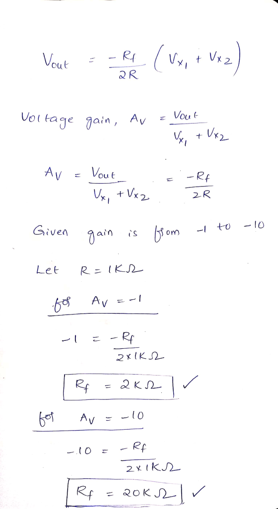
I am having some trouble finding the values of the Rf
(potentiometer) and R resistors for the following circuit (Right
Leg Driver (RLD)). The circuit should have an adjustable gain from
-1 to -10, and a 100kOhm output protection resistor (Ro). When I
wrote the expression of the gain, I could not find the values of Rf
and R that satisfies the abovementioned condition. 
Homework Answers
If you have any doubt ask in the comment section below.


Add Answer to:
I am having some trouble finding the values of the Rf
(potentiometer) and R resistors for...
I am having trouble calculating the loaded current (IL) and the bleeding current (I2) FIGURE 10.1...
 I
am having trouble calculating the loaded current (IL) and the
bleeding current (I2)
FIGURE 10.1 LAB PREPARATION Review Section 6.3 of Electronics Technology Fundamentals MATERIALS 1 DMM 1 variable de power supply Pretoboard 9 resistors: 100 2247 K2, 10 kA (2) X2 XKA. 1 2 3 and 1009 1 100 potentiometer PROCEDURE 1. Calculate the no-load output voltage and bleeder current for the circuit shown in Figure 10.2. Enter your calculations in Table 10.1. SR 10kn 10 V 6R...
I
am having trouble calculating the loaded current (IL) and the
bleeding current (I2)
FIGURE 10.1 LAB PREPARATION Review Section 6.3 of Electronics Technology Fundamentals MATERIALS 1 DMM 1 variable de power supply Pretoboard 9 resistors: 100 2247 K2, 10 kA (2) X2 XKA. 1 2 3 and 1009 1 100 potentiometer PROCEDURE 1. Calculate the no-load output voltage and bleeder current for the circuit shown in Figure 10.2. Enter your calculations in Table 10.1. SR 10kn 10 V 6R...
Q1. You are given a 12 V DC power supply. You are expected to develop a voltage divider to achieve a voltage of no...
 Q1. You are given a 12 V DC power supply. You are expected to develop a voltage divider to achieve a voltage of nominal 5V value using a pair of resistors from the E 12 range, with the restrition that you are not expected to draw a current of more than 1 mA from the 12 V DC supply i. Develop a simple circuit showing the possible values for each resistor pair, and the range of the DC output possible...
You are required to design a 2-stage voltage amplifier (find values for RE, RC1, RC2) to meet the following criteria: an...
 You are required to design a 2-stage voltage amplifier (find
values for RE, RC1, RC2) to meet the following criteria: an input
resistance of 400 kΩ and an overall voltage gain equal to or
greater than 250, with a resistor output load, RL. Use a
common-emitter with emitter degradation (RE) stage for the input,
followed by a commonemitter amplifier with bias current equal to
0.5 mA. (VCC = 20 V, βo = 200 and the DC levels of the first...
You are required to design a 2-stage voltage amplifier (find
values for RE, RC1, RC2) to meet the following criteria: an input
resistance of 400 kΩ and an overall voltage gain equal to or
greater than 250, with a resistor output load, RL. Use a
common-emitter with emitter degradation (RE) stage for the input,
followed by a commonemitter amplifier with bias current equal to
0.5 mA. (VCC = 20 V, βo = 200 and the DC levels of the first...
c) In estimating DC imperfections (input offset voltage, input offset current and the inverting amplifier with...
 c) In estimating DC imperfections (input offset voltage, input offset current and the inverting amplifier with nominal gain of -100 using 1 current) of an op-map, an and 10MQ resistors is implemented using the op-amp as shown in Fig 2(a) below R2 10MQ R 100k Vi Vo Figure 2(a): Inverting amplifier Measurements are conducted on the output voltage of the inverting amplifier under the following conditions: (i) the input (V) is open circuited and the output voltage is found to...
I am working on the divide/conquer algorithm. I am having a trouble with a print for...
I am working on the divide/conquer algorithm. I am having a trouble with a print for output from reading the file. Here is my work. When you see I put the comment with TODO. that one I am struck with readfile. I wonder if you'd able to help me to fix the readfile to find a single number. Here is the input3.txt (1 12 13 24 35 46 57 58 69). after that, the output should be 0. int mergeInversion(int...
Question 2: Conditioning CIPeuIL A. The circuit in Figure 1 is used to amplify the input...
 Question 2: Conditioning CIPeuIL A. The circuit in Figure 1 is used to amplify the input signal sh output waveform, labelling both the x and y axis (both numb and explain in detail why the signal has the shape it hass and labels) necessary calculations to support your answer. it has, including any 23ks2 +10V 2.3kΩ sin(10t)V10V Figure 1 B. The circuit in Figure 2 is a full ECG amplifier circuit. Page 2 of6 47 nF UA 1 k2 33...
Please show all written work as I am having trouble finding my way through the solution...
 Please show all written work as I am having trouble finding my
way through the solution to this problem. Thank you in advance!
Question 4 (12 points: 1, 2, 2, 2, 5) Consider the three-stage process shown here (a) What is the minimum TPT? (b) Calculate hourly capacity of each stage. G1 6 min 6 min D1 4 min W2 G2 6 min min Consider the following schedule. Jobs are numbered 1, 2, 3, 4 and so on. Jobs are...
Please show all written work as I am having trouble finding my
way through the solution to this problem. Thank you in advance!
Question 4 (12 points: 1, 2, 2, 2, 5) Consider the three-stage process shown here (a) What is the minimum TPT? (b) Calculate hourly capacity of each stage. G1 6 min 6 min D1 4 min W2 G2 6 min min Consider the following schedule. Jobs are numbered 1, 2, 3, 4 and so on. Jobs are...
I am currently trying to figure out the experiment below. Please complete Table 1 with an...
 I am currently trying to figure out the experiment below. Please
complete Table 1 with an explanation, I appreciate it thank
you! Promise to give thumbs up!
Introduction The phase differences between the output voltage, the voltage across the inductor, the voltage across the capacitor, and the voltage across the resistor will be examined at resonant frequency. The voltage and phase relationship will also be examined for frequencies above and below resonance. Theory An inductor, a capacitor, and a resistor are...
I am currently trying to figure out the experiment below. Please
complete Table 1 with an explanation, I appreciate it thank
you! Promise to give thumbs up!
Introduction The phase differences between the output voltage, the voltage across the inductor, the voltage across the capacitor, and the voltage across the resistor will be examined at resonant frequency. The voltage and phase relationship will also be examined for frequencies above and below resonance. Theory An inductor, a capacitor, and a resistor are...
 I
am having trouble calculating the loaded current (IL) and the
bleeding current (I2)
FIGURE 10.1 LAB PREPARATION Review Section 6.3 of Electronics Technology Fundamentals MATERIALS 1 DMM 1 variable de power supply Pretoboard 9 resistors: 100 2247 K2, 10 kA (2) X2 XKA. 1 2 3 and 1009 1 100 potentiometer PROCEDURE 1. Calculate the no-load output voltage and bleeder current for the circuit shown in Figure 10.2. Enter your calculations in Table 10.1. SR 10kn 10 V 6R...
I
am having trouble calculating the loaded current (IL) and the
bleeding current (I2)
FIGURE 10.1 LAB PREPARATION Review Section 6.3 of Electronics Technology Fundamentals MATERIALS 1 DMM 1 variable de power supply Pretoboard 9 resistors: 100 2247 K2, 10 kA (2) X2 XKA. 1 2 3 and 1009 1 100 potentiometer PROCEDURE 1. Calculate the no-load output voltage and bleeder current for the circuit shown in Figure 10.2. Enter your calculations in Table 10.1. SR 10kn 10 V 6R...
 Q1. You are given a 12 V DC power supply. You are expected to develop a voltage divider to achieve a voltage of nominal 5V value using a pair of resistors from the E 12 range, with the restrition that you are not expected to draw a current of more than 1 mA from the 12 V DC supply i. Develop a simple circuit showing the possible values for each resistor pair, and the range of the DC output possible...
 You are required to design a 2-stage voltage amplifier (find
values for RE, RC1, RC2) to meet the following criteria: an input
resistance of 400 kΩ and an overall voltage gain equal to or
greater than 250, with a resistor output load, RL. Use a
common-emitter with emitter degradation (RE) stage for the input,
followed by a commonemitter amplifier with bias current equal to
0.5 mA. (VCC = 20 V, βo = 200 and the DC levels of the first...
You are required to design a 2-stage voltage amplifier (find
values for RE, RC1, RC2) to meet the following criteria: an input
resistance of 400 kΩ and an overall voltage gain equal to or
greater than 250, with a resistor output load, RL. Use a
common-emitter with emitter degradation (RE) stage for the input,
followed by a commonemitter amplifier with bias current equal to
0.5 mA. (VCC = 20 V, βo = 200 and the DC levels of the first...
 c) In estimating DC imperfections (input offset voltage, input offset current and the inverting amplifier with nominal gain of -100 using 1 current) of an op-map, an and 10MQ resistors is implemented using the op-amp as shown in Fig 2(a) below R2 10MQ R 100k Vi Vo Figure 2(a): Inverting amplifier Measurements are conducted on the output voltage of the inverting amplifier under the following conditions: (i) the input (V) is open circuited and the output voltage is found to...
 Question 2: Conditioning CIPeuIL A. The circuit in Figure 1 is used to amplify the input signal sh output waveform, labelling both the x and y axis (both numb and explain in detail why the signal has the shape it hass and labels) necessary calculations to support your answer. it has, including any 23ks2 +10V 2.3kΩ sin(10t)V10V Figure 1 B. The circuit in Figure 2 is a full ECG amplifier circuit. Page 2 of6 47 nF UA 1 k2 33...
 Please show all written work as I am having trouble finding my
way through the solution to this problem. Thank you in advance!
Question 4 (12 points: 1, 2, 2, 2, 5) Consider the three-stage process shown here (a) What is the minimum TPT? (b) Calculate hourly capacity of each stage. G1 6 min 6 min D1 4 min W2 G2 6 min min Consider the following schedule. Jobs are numbered 1, 2, 3, 4 and so on. Jobs are...
Please show all written work as I am having trouble finding my
way through the solution to this problem. Thank you in advance!
Question 4 (12 points: 1, 2, 2, 2, 5) Consider the three-stage process shown here (a) What is the minimum TPT? (b) Calculate hourly capacity of each stage. G1 6 min 6 min D1 4 min W2 G2 6 min min Consider the following schedule. Jobs are numbered 1, 2, 3, 4 and so on. Jobs are...
 I am currently trying to figure out the experiment below. Please
complete Table 1 with an explanation, I appreciate it thank
you! Promise to give thumbs up!
Introduction The phase differences between the output voltage, the voltage across the inductor, the voltage across the capacitor, and the voltage across the resistor will be examined at resonant frequency. The voltage and phase relationship will also be examined for frequencies above and below resonance. Theory An inductor, a capacitor, and a resistor are...
I am currently trying to figure out the experiment below. Please
complete Table 1 with an explanation, I appreciate it thank
you! Promise to give thumbs up!
Introduction The phase differences between the output voltage, the voltage across the inductor, the voltage across the capacitor, and the voltage across the resistor will be examined at resonant frequency. The voltage and phase relationship will also be examined for frequencies above and below resonance. Theory An inductor, a capacitor, and a resistor are...
Most questions answered within 3 hours.
-
Identify and describe in detail the four categories of
institutions that could be included in a...
asked 3 minutes ago -
In python
class Customer:
def __init__(self, customer_id, last_name, first_name, phone_number, address):
self._customer_id = int(customer_id)
self._last_name =...
asked 11 minutes ago -
What is an example of a limitation in implementing a new
ERP system and how it...
asked 6 minutes ago -
In a section of 9.7cm of an artery with a radius of 2.6mm there
is a...
asked 7 minutes ago -
the two carboxylic acid groups of aspartic acid have different
acidities with pKa values of 2.1...
asked 11 minutes ago -
Would CuCO3 aqueous salt combined with calcium chloride
form a solid precipitate? If so, what would...
asked 10 minutes ago -
How do ECM Solutions assist in embedding a culture of continuous
improvement in an organization? (Project...
asked 30 minutes ago -
Directions
These directions introduce the idea of Essential Questions.
Since this may be a new concept...
asked 32 minutes ago -
1.b. Fiscal policy is said to suffer from ‘crowding out’.
Explain what this means and why...
asked 50 minutes ago -
The equation for the reaction of nitrogen and oxygen to form
nitrogen oxide is written as...
asked 54 minutes ago -
A scientist reproducing some photoelectric effect experiments
shines a light on a metal electrode, but doesn't...
asked 57 minutes ago -
In a study designed to test the effectiveness of magnets for
treating back pain, 35 patients...
asked 1 hour ago