
please solve it step by step with details
thank you!!!!!
Homework Answers
Request Answer!
We need at least 10 more requests to produce the answer.
0 / 10 have requested this problem solution
The more requests, the faster the answer.
Add Answer to:
please solve it step by step with details
thank you!!!!!
Water is to be pumped from...
Question 3: Water is to be pumped from one large, open tank to a second large,...
 Question 3: Water is to be pumped from one large, open tank to a second large, open tank. The water surface of the first tank is 5 ft lower than the water surface of the second tank. The pipe diameter throughout is 4in. The total length of pipe is 300ft. The friction coefficient is 0.02. The pump with the performance curve given in the figure is suggested by the engineer. With this pump, what would be the flow rate between...
2 The industrial coolant with density of 900 kg/m' is to be pumped from large open...
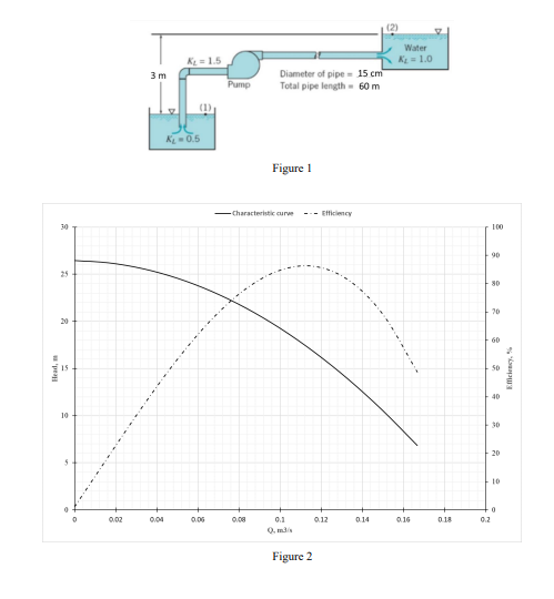
 2 The industrial coolant with density of 900 kg/m' is to be pumped from large open processing tank to a large open storage tank. The pipe diameter throughout the length of the pipe is 0.153 m and the total length of the pipe between the pipe entrance and pipe exit is 200 m. The Minor loss coefficients for the entrance and exit effects are 1 and 1.5. The experimental values of minor loss coefficients due to the elbows are calculated...
The industrial coolant with density of 900 kg/m' is to be pumped from large open processing...
 The industrial coolant with density of 900 kg/m' is to be pumped from large open processing tank to a large open storage tank. The pipe diameter throughout the length of the pipe is 0.153 m and the total length of the pipe between the pipe entrance and pipe exit is 200 m. The Minor loss coefficients for the entrance and exit effects are 1 and 1.5. The experimental values of minor loss coefficients due to the elbows are calculated as...
Water (density 998 kg/mº, dynamic viscosity 0.001 Pa s) is pumped between two reservoirs at a...
 Water (density 998 kg/mº, dynamic viscosity 0.001 Pa s) is pumped between two reservoirs at a volumetric flow rate of 0.006 m/s through a 120-m long pipe of 5 cm diameter. The roughness ratio of the pipe is a/d = 0.001. There are some fittings and valves in the pipe system, as shown in Figure Q1. The loss coefficients of the valves and fittings can be found in Table Q1. The Darcy friction factor can be found in the Moody...
(b) A schematic diagram of a simple transport system designed to transport oil over a lon distanc...
 (b) A schematic diagram of a simple transport system designed to transport oil over a lon distance. A schematic diagram of the system is illustrated in Figure 3(b). The elevations of free surfaces of tanks 1 and 2 from a common ground level are measured to be 100 m and 145 m respectively. The tanks are connected with 300-m long a circular pipe of diameter 50 cm The supply curve of the pump connected is given in Figure 3(c) Express...
10. Problem 12.38 from the textbook (Statement: In a chemical processing plant a liquid is pumped...
 10. Problem 12.38 from the textbook (Statement: In a chemical processing plant a liquid is pumped from an open tank, through a 0.1-m-diameter vertical pipe, and into another open tank as shown in the figure (a). A valve is located in the pipe, and the minor loss coefficient for the valve as a function of the valve setting is shown in figure (b). The pump head capacity relationship is given by the equation ha =52.0-1.01x10?Q? with ha in meters when...
Notre Dame University Faculty of Engineering Mechanical Engineering Dep Water flows through cast iron pipes and between the two tanks shown in Figure P4. The free sharp edge entrance. Bd by a dis...
 Notre Dame University Faculty of Engineering Mechanical Engineering Dep Water flows through cast iron pipes and between the two tanks shown in Figure P4. The free sharp edge entrance. Bd by a distance of 8 m. The water leaves Tank 1 through a contains a regular 90 threaded elbow and two unknown a regular 90° threaded elbow and a fully Branch pipeline 1 contains a regular 90 valves (valve 1 and valve 2). Branch pipeline 2 contains open gate valve....
Water at 15° is flowing at the rate of 14.4m²/hr (Fig. 2). The head added by...
 Water at 15° is flowing at the rate of 14.4m²/hr (Fig. 2). The head added by the pump is equivalent to 80 m. Both tanks are vented. Suction line is 15m long and discharge line is 200m long. Both suction and discharge lines are standard 2-inch (5.1cm) clean steel pipe with roughness value of ε = 5.1 x 10⁸m. Assume that the entrance from Tankl is through a rounded inlet with inlet radius of 10mm and that the elbows are...
 Question 3: Water is to be pumped from one large, open tank to a second large, open tank. The water surface of the first tank is 5 ft lower than the water surface of the second tank. The pipe diameter throughout is 4in. The total length of pipe is 300ft. The friction coefficient is 0.02. The pump with the performance curve given in the figure is suggested by the engineer. With this pump, what would be the flow rate between...
 2 The industrial coolant with density of 900 kg/m' is to be pumped from large open processing tank to a large open storage tank. The pipe diameter throughout the length of the pipe is 0.153 m and the total length of the pipe between the pipe entrance and pipe exit is 200 m. The Minor loss coefficients for the entrance and exit effects are 1 and 1.5. The experimental values of minor loss coefficients due to the elbows are calculated...
 The industrial coolant with density of 900 kg/m' is to be pumped from large open processing tank to a large open storage tank. The pipe diameter throughout the length of the pipe is 0.153 m and the total length of the pipe between the pipe entrance and pipe exit is 200 m. The Minor loss coefficients for the entrance and exit effects are 1 and 1.5. The experimental values of minor loss coefficients due to the elbows are calculated as...
 Water (density 998 kg/mº, dynamic viscosity 0.001 Pa s) is pumped between two reservoirs at a volumetric flow rate of 0.006 m/s through a 120-m long pipe of 5 cm diameter. The roughness ratio of the pipe is a/d = 0.001. There are some fittings and valves in the pipe system, as shown in Figure Q1. The loss coefficients of the valves and fittings can be found in Table Q1. The Darcy friction factor can be found in the Moody...
 (b) A schematic diagram of a simple transport system designed to transport oil over a lon distance. A schematic diagram of the system is illustrated in Figure 3(b). The elevations of free surfaces of tanks 1 and 2 from a common ground level are measured to be 100 m and 145 m respectively. The tanks are connected with 300-m long a circular pipe of diameter 50 cm The supply curve of the pump connected is given in Figure 3(c) Express...
 10. Problem 12.38 from the textbook (Statement: In a chemical processing plant a liquid is pumped from an open tank, through a 0.1-m-diameter vertical pipe, and into another open tank as shown in the figure (a). A valve is located in the pipe, and the minor loss coefficient for the valve as a function of the valve setting is shown in figure (b). The pump head capacity relationship is given by the equation ha =52.0-1.01x10?Q? with ha in meters when...
 Notre Dame University Faculty of Engineering Mechanical Engineering Dep Water flows through cast iron pipes and between the two tanks shown in Figure P4. The free sharp edge entrance. Bd by a distance of 8 m. The water leaves Tank 1 through a contains a regular 90 threaded elbow and two unknown a regular 90° threaded elbow and a fully Branch pipeline 1 contains a regular 90 valves (valve 1 and valve 2). Branch pipeline 2 contains open gate valve....
 Notre Dame University Faculty of Engineering Mechanical Engineering Dep Water flows through cast iron pipes and between the two tanks shown in Figure P4. The free sharp edge entrance. Bd by a distance of 8 m. The water leaves Tank 1 through a contains a regular 90 threaded elbow and two unknown a regular 90° threaded elbow and a fully Branch pipeline 1 contains a regular 90 valves (valve 1 and valve 2). Branch pipeline 2 contains open gate valve....
 Notre Dame University Faculty of Engineering Mechanical Engineering Dep Water flows through cast iron pipes and between the two tanks shown in Figure P4. The free sharp edge entrance. Bd by a distance of 8 m. The water leaves Tank 1 through a contains a regular 90 threaded elbow and two unknown a regular 90° threaded elbow and a fully Branch pipeline 1 contains a regular 90 valves (valve 1 and valve 2). Branch pipeline 2 contains open gate valve....
 Water at 15° is flowing at the rate of 14.4m²/hr (Fig. 2). The head added by the pump is equivalent to 80 m. Both tanks are vented. Suction line is 15m long and discharge line is 200m long. Both suction and discharge lines are standard 2-inch (5.1cm) clean steel pipe with roughness value of ε = 5.1 x 10⁸m. Assume that the entrance from Tankl is through a rounded inlet with inlet radius of 10mm and that the elbows are...
Most questions answered within 3 hours.
-
While rotating the tires on your car you notice a rock [mass =
0.1 Kg] stuck...
asked 1 hour ago -
Using MARS simulator, write MIPS programs according to
the following scenarios: Receive a positive integer number...
asked 3 hours ago -
An object in front of a concave mirror has a real image that is
11.5 cm...
asked 3 hours ago -
Consider the reaction, C3 H8 + O2 --> CO2 + H2O. How many
moles of O2...
asked 5 hours ago -
You and your opponent both roll a fair die. If you both roll the
same number,...
asked 5 hours ago -
In a study of the accuracy of fast food drive-through orders,
Restaurant A had 257 accurate...
asked 5 hours ago -
Identify and describe in detail the four categories of
institutions that could be included in a...
asked 5 hours ago -
In python
class Customer:
def __init__(self, customer_id, last_name, first_name, phone_number, address):
self._customer_id = int(customer_id)
self._last_name =...
asked 5 hours ago -
What is an example of a limitation in implementing a new
ERP system and how it...
asked 5 hours ago -
In a section of 9.7cm of an artery with a radius of 2.6mm there
is a...
asked 5 hours ago -
the two carboxylic acid groups of aspartic acid have different
acidities with pKa values of 2.1...
asked 5 hours ago -
Would CuCO3 aqueous salt combined with calcium chloride
form a solid precipitate? If so, what would...
asked 5 hours ago