In the lecture we demonstrated how an active low, synchronous clear feature can be synthesized into...
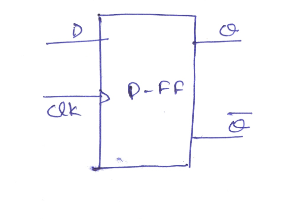
In the lecture we demonstrated how an active low, synchronous clear feature can be synthesized into a D flip-flop. For this task, please synthesize a D flip-flop that has an active low, synchronous preset feature added to it. Label the preset input signal as “preset_n”.
Homework Answers
The truth table of the D flip flop is
| CLK | D | Qn+1 |
| 0 | 0 | Qn |
| 0 | 1 | Qn |
| 1 | 0 | 0 |
| 1 | 1 | 1 |
for a high clock 1 Qn+1= D
The preset signal will force Qn+1 to 1 irrespective of clock and D.
| Qn | Preset_n(bar) | Qn+1 | Qn+1(bar) |
| 0 | 0 | 1 | 0 |
| 0 | 1 | 0 | 1 |
| 1 | 0 | 1 | 0 |
| 1 | 1 | 1 | 0 |


Verilog code for the synthesis of D flip flop with Preset_n.
module dff_syspr (D, clk, preset_n, q);
input D, clk, preset_n;
output q;
reg q;
always @ (posedge clk)
if (~preset_n)
q = 1'b1;
else
q = data;
endmodule
Add Answer to:
In the lecture we demonstrated how an active low, synchronous
clear feature can be synthesized into...
Write the verilog code that implements a negitive edge D-Flip Flop with asynchronous active low preset...
Write the verilog code that implements a negitive edge D-Flip Flop with asynchronous active low preset and clear I have : module dff( preset, clear, clk, D, Q) input preset; input clear; input clk; input D; output Q; reg Q; always @ (negedge clk or negedge preset or negedge clear); if (preset); Q = 0; else (clear == 0); Q = D; endmodule I honestly just want to know if i'm doing this right or not, if im not correct,...
Each FF has an asynchronous active-low clear signal. The asynchronous active-low clear signal clears the FF and uses this signal to set the initial output of the FF to zero. (Active-low clear: clear...
Each FF has an asynchronous active-low clear signal. The asynchronous active-low clear signal clears the FF and uses this signal to set the initial output of the FF to zero. (Active-low clear: clear when clear signal is low (0)). Implement negative edge-triggered T FF using Verilog code. At this time, The interface is as follows. Module t_ff (input t, input clk, input clearb, output q); How the waveform of q changes when the value of input t changes sequentially to...
1. a) Complete the waveform templates for the Master –Slave D-flip-flop below with given D, CLK,...
 1.
a) Complete the waveform templates for the Master –Slave
D-flip-flop below with given D, CLK, CLEAR, and PRESET signals.
Neglect the propagation delays.
b) Does it have positive or negative edge triggering with
respect to CLK?
c) Are the asynchronous PRESET and CLEAR active-high or
active-low?
2. Enabling of data load in the D-flip-flop was implemented with
a 2-to-1 multiplexer as show below. The D-flip-flop has the
positive edge triggering and the active-low asynchronous clear.
a) Is the Enable...
1.
a) Complete the waveform templates for the Master –Slave
D-flip-flop below with given D, CLK, CLEAR, and PRESET signals.
Neglect the propagation delays.
b) Does it have positive or negative edge triggering with
respect to CLK?
c) Are the asynchronous PRESET and CLEAR active-high or
active-low?
2. Enabling of data load in the D-flip-flop was implemented with
a 2-to-1 multiplexer as show below. The D-flip-flop has the
positive edge triggering and the active-low asynchronous clear.
a) Is the Enable...
a. How many s are oquinst to build a binary counter that counts tihom 0 to 102" s Determine he fhroquensy at the outpst of the last FF of this counter for an input clock trequneney What is the...
 a. How many s are oquinst to build a binary counter that counts tihom 0 to 102" s Determine he fhroquensy at the outpst of the last FF of this counter for an input clock trequneney What is the counter's MOD number? d If the counter is initially at zero, what counter will it hold after 2060 pulses? 9 Cnsider the timing diagram shown below for JK Flip Flop (NOR), Complete the output waveform for Q clock IK Apply the...
The lab can be made in orcad but all I need is how to and the...
 The lab can be made in orcad but all I need is how to
and the design. Please Read the problem carefully and answer as
much as you can. Thank you!!!
Part 2 T and D from JK 1. Using part 74107 (JK flip-flop), build a T and a D-flip. Do NOT put both designs on the same schematic page or in the same folder. 2. Create parts for each and run a simulation using the parts created. Part 3....
The lab can be made in orcad but all I need is how to
and the design. Please Read the problem carefully and answer as
much as you can. Thank you!!!
Part 2 T and D from JK 1. Using part 74107 (JK flip-flop), build a T and a D-flip. Do NOT put both designs on the same schematic page or in the same folder. 2. Create parts for each and run a simulation using the parts created. Part 3....
Answers are at the end of the chapter 1. If an S-R latch has a 1...
 Answers are at the end of the chapter 1. If an S-R latch has a 1 on the S input and a 0 on the R input and then the S input goes to 0, the latch will be (a) set (b) reset (c) invalid (d) clear 2. The invalid state of an S-R latch occurs when (c) S 1,R-1 (d) S-0, R-O 3. For a gated D latch, the output always equals the D input (a) before the enable...
Pre-Laboratorv Exercise: You are to design a state machine capable of controlling a 4-phase unipo...
 Pre-Laboratorv Exercise: You are to design a state machine capable of controlling a 4-phase unipolar stepper motor. This motor operates by energizing one (or more) of four coils of wire at a time to rotate a magnetized shaft to predetermined positions. Let us call the four coils A, B, C, and D. To make the motor rotate properly, the coils need to be turned on (driven at logic "1") and off (driven at logic "O") in the following sequence: ABCD-...
Consider the circuit in Figure 1. It is a 4-bit (QQ2Q3) synchronous counter which uses four T-typ...
 Consider the circuit in Figure 1. It is a 4-bit (QQ2Q3) synchronous counter which uses four T-type flip-flops. The counter increases its value on each positive edge of the clock if the Enable signal is asserted. The counter is reset to 0 by setting the Clear signal low. You are to implement an 8-bit counter of this type Enable T Q Clock Clear Figure 1. 4-bit synchronous counter (but you need to implement 8-bit counter in this lab) Specific notes:...
Can someone please show me a circuit diagram so i can see how to construct this...
 Can someone please show me a circuit diagram so i can see how to
construct this on a bread board i am id 6 yhanks in advance
EEET-2251: Course & Projoct Guide 2018 EEET-2251: Cousc &Projoct Guide 2018 affic Light Controller A single switch must set your HC74 based state machine to the initial state (the U state This lab will get you to design a simple controller for a pedestrian crossing based on synchronous digital logic. You will master...
Can someone please show me a circuit diagram so i can see how to
construct this on a bread board i am id 6 yhanks in advance
EEET-2251: Course & Projoct Guide 2018 EEET-2251: Cousc &Projoct Guide 2018 affic Light Controller A single switch must set your HC74 based state machine to the initial state (the U state This lab will get you to design a simple controller for a pedestrian crossing based on synchronous digital logic. You will master...
please answer all thanks very much! Question 3 Shown below is a schematic diagram of a...
 please answer all thanks very much!
Question 3 Shown below is a schematic diagram of a counter made up of three JK flip-flops. (d) Shown below is a master-slave D flip-flop. This is made using two gated D latches. The truth table for a gated D latch is also shown below. HIGH J J CLK ас ас ac Truth table: gated D latch D EN D D, Q. D, 0. 0 0 go CLK ΕΝΟ ENO: 0 0 1 0...
please answer all thanks very much!
Question 3 Shown below is a schematic diagram of a counter made up of three JK flip-flops. (d) Shown below is a master-slave D flip-flop. This is made using two gated D latches. The truth table for a gated D latch is also shown below. HIGH J J CLK ас ас ac Truth table: gated D latch D EN D D, Q. D, 0. 0 0 go CLK ΕΝΟ ENO: 0 0 1 0...
 1.
a) Complete the waveform templates for the Master –Slave
D-flip-flop below with given D, CLK, CLEAR, and PRESET signals.
Neglect the propagation delays.
b) Does it have positive or negative edge triggering with
respect to CLK?
c) Are the asynchronous PRESET and CLEAR active-high or
active-low?
2. Enabling of data load in the D-flip-flop was implemented with
a 2-to-1 multiplexer as show below. The D-flip-flop has the
positive edge triggering and the active-low asynchronous clear.
a) Is the Enable...
1.
a) Complete the waveform templates for the Master –Slave
D-flip-flop below with given D, CLK, CLEAR, and PRESET signals.
Neglect the propagation delays.
b) Does it have positive or negative edge triggering with
respect to CLK?
c) Are the asynchronous PRESET and CLEAR active-high or
active-low?
2. Enabling of data load in the D-flip-flop was implemented with
a 2-to-1 multiplexer as show below. The D-flip-flop has the
positive edge triggering and the active-low asynchronous clear.
a) Is the Enable...
 a. How many s are oquinst to build a binary counter that counts tihom 0 to 102" s Determine he fhroquensy at the outpst of the last FF of this counter for an input clock trequneney What is the counter's MOD number? d If the counter is initially at zero, what counter will it hold after 2060 pulses? 9 Cnsider the timing diagram shown below for JK Flip Flop (NOR), Complete the output waveform for Q clock IK Apply the...
 The lab can be made in orcad but all I need is how to
and the design. Please Read the problem carefully and answer as
much as you can. Thank you!!!
Part 2 T and D from JK 1. Using part 74107 (JK flip-flop), build a T and a D-flip. Do NOT put both designs on the same schematic page or in the same folder. 2. Create parts for each and run a simulation using the parts created. Part 3....
The lab can be made in orcad but all I need is how to
and the design. Please Read the problem carefully and answer as
much as you can. Thank you!!!
Part 2 T and D from JK 1. Using part 74107 (JK flip-flop), build a T and a D-flip. Do NOT put both designs on the same schematic page or in the same folder. 2. Create parts for each and run a simulation using the parts created. Part 3....
 Answers are at the end of the chapter 1. If an S-R latch has a 1 on the S input and a 0 on the R input and then the S input goes to 0, the latch will be (a) set (b) reset (c) invalid (d) clear 2. The invalid state of an S-R latch occurs when (c) S 1,R-1 (d) S-0, R-O 3. For a gated D latch, the output always equals the D input (a) before the enable...
 Pre-Laboratorv Exercise: You are to design a state machine capable of controlling a 4-phase unipolar stepper motor. This motor operates by energizing one (or more) of four coils of wire at a time to rotate a magnetized shaft to predetermined positions. Let us call the four coils A, B, C, and D. To make the motor rotate properly, the coils need to be turned on (driven at logic "1") and off (driven at logic "O") in the following sequence: ABCD-...
 Consider the circuit in Figure 1. It is a 4-bit (QQ2Q3) synchronous counter which uses four T-type flip-flops. The counter increases its value on each positive edge of the clock if the Enable signal is asserted. The counter is reset to 0 by setting the Clear signal low. You are to implement an 8-bit counter of this type Enable T Q Clock Clear Figure 1. 4-bit synchronous counter (but you need to implement 8-bit counter in this lab) Specific notes:...
 Can someone please show me a circuit diagram so i can see how to
construct this on a bread board i am id 6 yhanks in advance
EEET-2251: Course & Projoct Guide 2018 EEET-2251: Cousc &Projoct Guide 2018 affic Light Controller A single switch must set your HC74 based state machine to the initial state (the U state This lab will get you to design a simple controller for a pedestrian crossing based on synchronous digital logic. You will master...
Can someone please show me a circuit diagram so i can see how to
construct this on a bread board i am id 6 yhanks in advance
EEET-2251: Course & Projoct Guide 2018 EEET-2251: Cousc &Projoct Guide 2018 affic Light Controller A single switch must set your HC74 based state machine to the initial state (the U state This lab will get you to design a simple controller for a pedestrian crossing based on synchronous digital logic. You will master...
 please answer all thanks very much!
Question 3 Shown below is a schematic diagram of a counter made up of three JK flip-flops. (d) Shown below is a master-slave D flip-flop. This is made using two gated D latches. The truth table for a gated D latch is also shown below. HIGH J J CLK ас ас ac Truth table: gated D latch D EN D D, Q. D, 0. 0 0 go CLK ΕΝΟ ENO: 0 0 1 0...
please answer all thanks very much!
Question 3 Shown below is a schematic diagram of a counter made up of three JK flip-flops. (d) Shown below is a master-slave D flip-flop. This is made using two gated D latches. The truth table for a gated D latch is also shown below. HIGH J J CLK ас ас ac Truth table: gated D latch D EN D D, Q. D, 0. 0 0 go CLK ΕΝΟ ENO: 0 0 1 0...
Most questions answered within 3 hours.
-
3) What are the typical social structures in a global city?
asked 1 hour ago -
Luther Corporation
Consolidated Balance Sheet
December 31, 2019 and 2018 (in $ millions)
Assets
2019
2018...
asked 1 hour ago -
(Expected rate of return and risk) Carter Inc. is evaluating a
security. Calculate the investment’s expected...
asked 3 hours ago -
What specific indicators can point to lack of progress for
African Americans in American society?
asked 4 hours ago -
1-The Electrons in a beam are moving at 2.7×10⁸ m/s in an
electric field of 15000...
asked 5 hours ago -
A gas tank is a vertical cylinder. It has a radius of 1m, a
height of...
asked 5 hours ago -
Accent Software faces the following conditions. All of these
support Accent’s use of a market-penetration pricing...
asked 6 hours ago -
A mathematically inclined friend emails you the following
instructions: "Meet me in the cafeteria the first...
asked 6 hours ago -
A monopoly sells in two countries . The demand curves in the two
countries are p1...
asked 7 hours ago -
A .15kg rubber ball is bounced off a wall. Before hitting the
wall, the ball moves...
asked 8 hours ago -
A manufacturing company preparing to build a new plant is
considering three potential locations for it....
asked 8 hours ago -
B. If compound Y has approximately the same values of solubility
in toluene as compound X,...
asked 9 hours ago