
Homework Answers

Add Answer to:
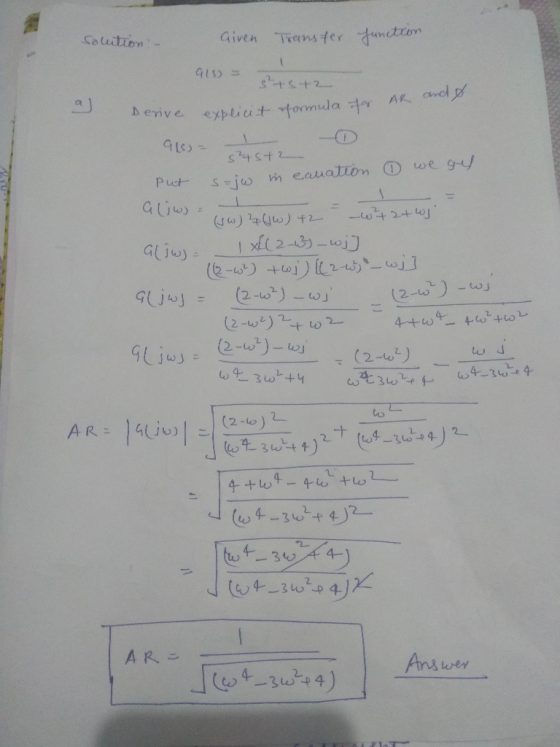
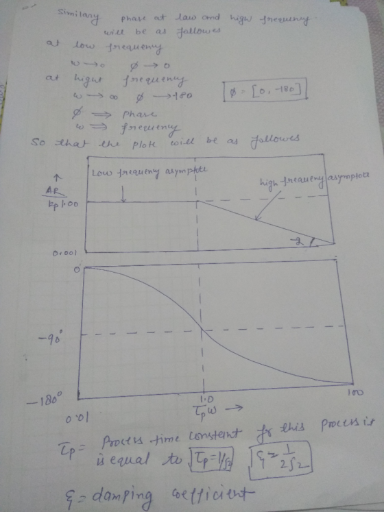
For the systems with the transfer functions given below. (a) Derive explicit formulas for AR and ...
For the circuit shown below (1) Please derive an expression for the transfer function H(jco)- Vout/Vin....
 For the circuit shown below (1) Please derive an expression for the transfer function H(jco)- Vout/Vin. (2) Sketch the corresponding Bode magnitude and phase plots, and please indicate the slope. 50Ω 250 mF 100 Ω 250 mF in out
Consider the system given below where K is a constant gain, Gp is the plant, and Ge is a compensator. The Bode Plots of a Gp is given below. Problem 1: Bode Diagram 20 2 40 -60 80 -100 90 135 180 a 2...
 Consider the system given below where K is a constant gain, Gp is the plant, and Ge is a compensator. The Bode Plots of a Gp is given below. Problem 1: Bode Diagram 20 2 40 -60 80 -100 90 135 180 a 225 270 101 10 Frequency (rad/s) 102 a. Looking at the low frequency behavior, determine its number of poles at origin. Explain. b. Looking at the high frequency behavior, determine the number of excess poles. Explain. C....
For the following closed-loop transfer functions, sketch the bode plots (magnitude and phase), id...
 For the following closed-loop transfer functions, sketch the bode plots (magnitude and phase), iden- tifying the zero gain, the slopes (in Decibels) and the high-frequency cutt-off rate. Then verify with Matlab (6) wn = 1, 〈 0.0.1, and 0.707. (8) Assuming the system of Problem 6 above, and an input of r(t) = 30sin(1000 t), use your bode plot to obtain the steady-state response
For the following closed-loop transfer functions, sketch the bode plots (magnitude and phase), iden- tifying the...
For the following closed-loop transfer functions, sketch the bode plots (magnitude and phase), iden- tifying the zero gain, the slopes (in Decibels) and the high-frequency cutt-off rate. Then verify with Matlab (6) wn = 1, 〈 0.0.1, and 0.707. (8) Assuming the system of Problem 6 above, and an input of r(t) = 30sin(1000 t), use your bode plot to obtain the steady-state response
For the following closed-loop transfer functions, sketch the bode plots (magnitude and phase), iden- tifying the...
For the following closed-loop transfer functions, sketch the bode plots (magnitude and phase), id...
 For the following closed-loop transfer functions, sketch the bode plots (magnitude and phase), iden- tifying the zero gain, the slopes (in Decibels) and the high-frequency cutt-off rate. Then verify with Matlab C()101 100) s 0.1) (s 10) 100 s(s +10)2 G(s) = (56) G(s) = s+10(s+100)
For the following closed-loop transfer functions, sketch the bode plots (magnitude and phase), iden- tifying the zero gain, the slopes (in Decibels) and the high-frequency cutt-off rate. Then verify with Matlab C()101 100) s...
For the following closed-loop transfer functions, sketch the bode plots (magnitude and phase), iden- tifying the zero gain, the slopes (in Decibels) and the high-frequency cutt-off rate. Then verify with Matlab C()101 100) s 0.1) (s 10) 100 s(s +10)2 G(s) = (56) G(s) = s+10(s+100)
For the following closed-loop transfer functions, sketch the bode plots (magnitude and phase), iden- tifying the zero gain, the slopes (in Decibels) and the high-frequency cutt-off rate. Then verify with Matlab C()101 100) s...
Problem 5: For the following transfer functions, sketch the bode asymptotic magnitude and phase p...
 Problem 5: For the following transfer functions, sketch the bode asymptotic magnitude and phase plots, find the Gain margin and Phase margin, find the system type and the corresponding error constant for each case. G(A) (s +3)(s +5) s(s +2) (s+4) S+5 2)b).
Problem 5: For the following transfer functions, sketch the bode asymptotic magnitude and phase plots, find the Gain margin and Phase margin, find the system type and the corresponding error constant for each case. G(A) (s +3)(s...
Problem 5: For the following transfer functions, sketch the bode asymptotic magnitude and phase plots, find the Gain margin and Phase margin, find the system type and the corresponding error constant for each case. G(A) (s +3)(s +5) s(s +2) (s+4) S+5 2)b).
Problem 5: For the following transfer functions, sketch the bode asymptotic magnitude and phase plots, find the Gain margin and Phase margin, find the system type and the corresponding error constant for each case. G(A) (s +3)(s...
D9.2 Design a state-feedback controller for the following systems. Determine the controller gains, open-loop transfer functions,...
 D9.2 Design a state-feedback controller for the following systems. Determine the controller gains, open-loop transfer functions, and closed-loop transfer functions Use the open-loop transfer functions to obtain root locus, Bode plots, and gain and phase margins LU u=-kx + r Closed-loop poles at s --1tj 2
2. Given the following transfer function S+ 2 Sketch the Bode plots, by marking the breakpoint frequencies, asymptotes...
 2. Given the following transfer function S+ 2 Sketch the Bode plots, by marking the breakpoint frequencies, asymptotes of the log modulus and phase angles. Show, by using complex algebra, that the values you find on the plots are correct 0 0 0 0 2 0 0 5 0 5 5 00000000001 28642
2. Given the following transfer function S+ 2 Sketch the Bode plots, by marking the breakpoint frequencies, asymptotes of the log modulus and phase angles. Show, by...
2. Given the following transfer function S+ 2 Sketch the Bode plots, by marking the breakpoint frequencies, asymptotes of the log modulus and phase angles. Show, by using complex algebra, that the values you find on the plots are correct 0 0 0 0 2 0 0 5 0 5 5 00000000001 28642
2. Given the following transfer function S+ 2 Sketch the Bode plots, by marking the breakpoint frequencies, asymptotes of the log modulus and phase angles. Show, by...
Consider three (causal) LTI systems, corresponding to transfer functions described (except for gain K) by the...
 Consider three (causal) LTI systems, corresponding to transfer functions described (except for gain K) by the following pole-zero plots. Im Im ++j10 X - -100 - 10 Re -10 : 5 * +-j10 Pole-Zero Plot for System A Pole-Zero Plot for System B Pole-Zero Plot for System C In each part below, determine which of the three systems can meet the given specifications, including any implications on what value(s) the transfer function's gain K must be. (a) (10 points) The...
3. You are given the following Bode diagrams for different systems. Find the transfer function for...
 3. You are given the following Bode diagrams for different systems. Find the transfer function for each one of the systems considering the asymptotes and breaking points. 2.5 An C. - - - Magnitude (dB) Magnitude (dB) 10-1 100 101 10% 10° Frequency (rad/s) Frequency (rad/s) Magnitude (dB) Magnitude (dB) 100 101 101 Frequency (rad/s) 100 101 10² Frequency (rad/s) 103 104
Please help 1. For the circuits shown in Figs. 3(a) and 3(b), derive the transfer functions...
 Please help
1. For the circuits shown in Figs. 3(a) and 3(b), derive the transfer functions in the following forms LP UL and express wL, WH, KL and KH in terms of resistors and capacitors HP Figure 3: First order (a) lowpass filter (b) highpass filter The frequencies wL and wH are known as: . Pole frequency, defined as the root of the denominator of H(s) . Corner frequency, defined as the frequency at which the gain is 0.707 times...
Please help
1. For the circuits shown in Figs. 3(a) and 3(b), derive the transfer functions in the following forms LP UL and express wL, WH, KL and KH in terms of resistors and capacitors HP Figure 3: First order (a) lowpass filter (b) highpass filter The frequencies wL and wH are known as: . Pole frequency, defined as the root of the denominator of H(s) . Corner frequency, defined as the frequency at which the gain is 0.707 times...
 For the circuit shown below (1) Please derive an expression for the transfer function H(jco)- Vout/Vin. (2) Sketch the corresponding Bode magnitude and phase plots, and please indicate the slope. 50Ω 250 mF 100 Ω 250 mF in out
 Consider the system given below where K is a constant gain, Gp is the plant, and Ge is a compensator. The Bode Plots of a Gp is given below. Problem 1: Bode Diagram 20 2 40 -60 80 -100 90 135 180 a 225 270 101 10 Frequency (rad/s) 102 a. Looking at the low frequency behavior, determine its number of poles at origin. Explain. b. Looking at the high frequency behavior, determine the number of excess poles. Explain. C....
 For the following closed-loop transfer functions, sketch the bode plots (magnitude and phase), iden- tifying the zero gain, the slopes (in Decibels) and the high-frequency cutt-off rate. Then verify with Matlab (6) wn = 1, 〈 0.0.1, and 0.707. (8) Assuming the system of Problem 6 above, and an input of r(t) = 30sin(1000 t), use your bode plot to obtain the steady-state response
For the following closed-loop transfer functions, sketch the bode plots (magnitude and phase), iden- tifying the...
For the following closed-loop transfer functions, sketch the bode plots (magnitude and phase), iden- tifying the zero gain, the slopes (in Decibels) and the high-frequency cutt-off rate. Then verify with Matlab (6) wn = 1, 〈 0.0.1, and 0.707. (8) Assuming the system of Problem 6 above, and an input of r(t) = 30sin(1000 t), use your bode plot to obtain the steady-state response
For the following closed-loop transfer functions, sketch the bode plots (magnitude and phase), iden- tifying the...
 For the following closed-loop transfer functions, sketch the bode plots (magnitude and phase), iden- tifying the zero gain, the slopes (in Decibels) and the high-frequency cutt-off rate. Then verify with Matlab C()101 100) s 0.1) (s 10) 100 s(s +10)2 G(s) = (56) G(s) = s+10(s+100)
For the following closed-loop transfer functions, sketch the bode plots (magnitude and phase), iden- tifying the zero gain, the slopes (in Decibels) and the high-frequency cutt-off rate. Then verify with Matlab C()101 100) s...
For the following closed-loop transfer functions, sketch the bode plots (magnitude and phase), iden- tifying the zero gain, the slopes (in Decibels) and the high-frequency cutt-off rate. Then verify with Matlab C()101 100) s 0.1) (s 10) 100 s(s +10)2 G(s) = (56) G(s) = s+10(s+100)
For the following closed-loop transfer functions, sketch the bode plots (magnitude and phase), iden- tifying the zero gain, the slopes (in Decibels) and the high-frequency cutt-off rate. Then verify with Matlab C()101 100) s...
 Problem 5: For the following transfer functions, sketch the bode asymptotic magnitude and phase plots, find the Gain margin and Phase margin, find the system type and the corresponding error constant for each case. G(A) (s +3)(s +5) s(s +2) (s+4) S+5 2)b).
Problem 5: For the following transfer functions, sketch the bode asymptotic magnitude and phase plots, find the Gain margin and Phase margin, find the system type and the corresponding error constant for each case. G(A) (s +3)(s...
Problem 5: For the following transfer functions, sketch the bode asymptotic magnitude and phase plots, find the Gain margin and Phase margin, find the system type and the corresponding error constant for each case. G(A) (s +3)(s +5) s(s +2) (s+4) S+5 2)b).
Problem 5: For the following transfer functions, sketch the bode asymptotic magnitude and phase plots, find the Gain margin and Phase margin, find the system type and the corresponding error constant for each case. G(A) (s +3)(s...
 D9.2 Design a state-feedback controller for the following systems. Determine the controller gains, open-loop transfer functions, and closed-loop transfer functions Use the open-loop transfer functions to obtain root locus, Bode plots, and gain and phase margins LU u=-kx + r Closed-loop poles at s --1tj 2
 2. Given the following transfer function S+ 2 Sketch the Bode plots, by marking the breakpoint frequencies, asymptotes of the log modulus and phase angles. Show, by using complex algebra, that the values you find on the plots are correct 0 0 0 0 2 0 0 5 0 5 5 00000000001 28642
2. Given the following transfer function S+ 2 Sketch the Bode plots, by marking the breakpoint frequencies, asymptotes of the log modulus and phase angles. Show, by...
2. Given the following transfer function S+ 2 Sketch the Bode plots, by marking the breakpoint frequencies, asymptotes of the log modulus and phase angles. Show, by using complex algebra, that the values you find on the plots are correct 0 0 0 0 2 0 0 5 0 5 5 00000000001 28642
2. Given the following transfer function S+ 2 Sketch the Bode plots, by marking the breakpoint frequencies, asymptotes of the log modulus and phase angles. Show, by...
 Consider three (causal) LTI systems, corresponding to transfer functions described (except for gain K) by the following pole-zero plots. Im Im ++j10 X - -100 - 10 Re -10 : 5 * +-j10 Pole-Zero Plot for System A Pole-Zero Plot for System B Pole-Zero Plot for System C In each part below, determine which of the three systems can meet the given specifications, including any implications on what value(s) the transfer function's gain K must be. (a) (10 points) The...
 3. You are given the following Bode diagrams for different systems. Find the transfer function for each one of the systems considering the asymptotes and breaking points. 2.5 An C. - - - Magnitude (dB) Magnitude (dB) 10-1 100 101 10% 10° Frequency (rad/s) Frequency (rad/s) Magnitude (dB) Magnitude (dB) 100 101 101 Frequency (rad/s) 100 101 10² Frequency (rad/s) 103 104
 Please help
1. For the circuits shown in Figs. 3(a) and 3(b), derive the transfer functions in the following forms LP UL and express wL, WH, KL and KH in terms of resistors and capacitors HP Figure 3: First order (a) lowpass filter (b) highpass filter The frequencies wL and wH are known as: . Pole frequency, defined as the root of the denominator of H(s) . Corner frequency, defined as the frequency at which the gain is 0.707 times...
Please help
1. For the circuits shown in Figs. 3(a) and 3(b), derive the transfer functions in the following forms LP UL and express wL, WH, KL and KH in terms of resistors and capacitors HP Figure 3: First order (a) lowpass filter (b) highpass filter The frequencies wL and wH are known as: . Pole frequency, defined as the root of the denominator of H(s) . Corner frequency, defined as the frequency at which the gain is 0.707 times...
Most questions answered within 3 hours.
-
All cells have a membrane potential but only excitable cells
like neurons or muscle cells can...
asked 8 minutes ago -
Suppose a quiz contains 20 true/false questions. You
know the correct answer to the first 10...
asked 36 minutes ago -
Is depression the cause or the effect of a stressful
situation? Explain.
12) How do learning...
asked 1 hour ago -
Critically discuss whether the Bretton Woods System has been
based on Keynesian principles. Please give me...
asked 2 hours ago -
An ammeter with a scale ranging from 0 to 15mA has a resistance
of 5Omega. How...
asked 3 hours ago -
def blur(img: Image) -> Image:
"""Blur Image, img, based on the given pixel_size
Hints:
- For...
asked 3 hours ago -
a
carboxylic acid reacting with a strong base will form what
ion
asked 4 hours ago -
which value if any in each pair corresponds to a
faster reaction k=18.k=137
asked 4 hours ago -
Bus lines can be separated into two generic types, dedicated and
multiplexed.
i. What is the...
asked 6 hours ago -
This is 'Branding' course which is part of marketing.
1. As a brand manager of Nudie...
asked 6 hours ago -
You are considering the purchase of a new stock. The stock is
forecasted to pay a...
asked 7 hours ago -
vector a has componets Ax and Ay, and makes an angle theta with
the y-axis. Select...
asked 7 hours ago