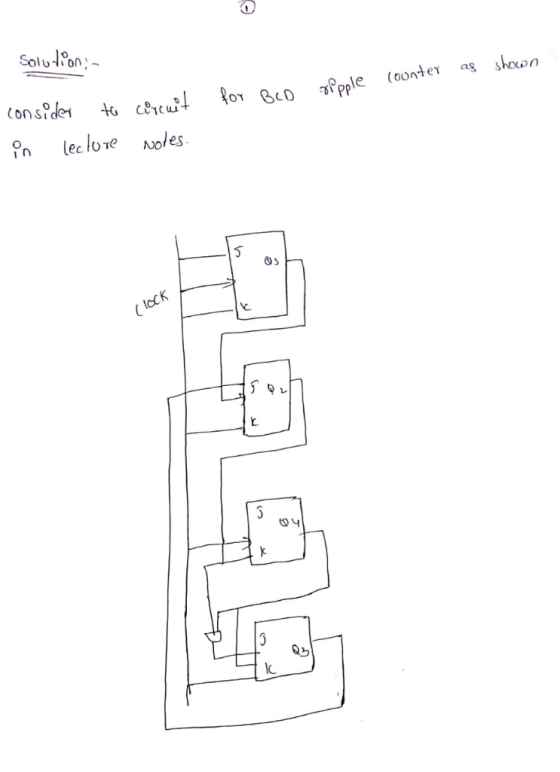
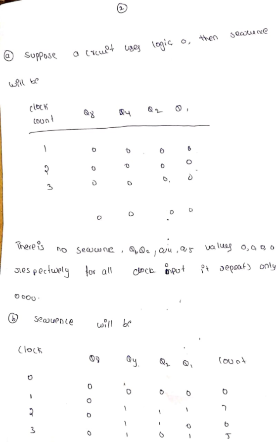
Consider the circuit for BCD ripple counter as shown in Lecture Notes. Consider the following mod...
Homework Answers

Add Answer to:
Consider the circuit for BCD ripple counter as shown in Lecture Notes. Consider the following mod...
(a) Design an asynchronous Binary Coded Decimal (BCD) count-up counter using JK flip-flops. Draw the counter circuit clearly showing the configuration of the JK flip-flops and the necessary logic gat...
 (a) Design an asynchronous Binary Coded Decimal (BCD) count-up counter using JK flip-flops. Draw the counter circuit clearly showing the configuration of the JK flip-flops and the necessary logic gate(s). Sketch the input and output waveforms of this counter (7 Marks) (b) The binary up/down counter for a cargo lift controller in a 7-storey building has an up-down (UID) control input and a buzzer output (B). The buzzer will sound B 1) when the lift is at level 1 or...
1. Answer the following questions related to Lecture 19 on registers and counters: . Consider the...
 1. Answer the following questions related to Lecture 19 on registers and counters: . Consider the serial adder on slide 10. Let registers A and B be bit shift registers, and assume that the Shift Control input is set to the "shift right" mode. Suppose that the initial contents of registers A, B, and the D flip flop are A-0110, B-0011, and Q-0. What are the contents of A, B and the D lip flop.. - after one clock edge....
A pulse-generating circuit generates eight repetitive pulses as shown in the figure. Implement the pulse-generating circuit using the counter circuits listed and a minimum of gate logic. Use J-K flip...
 A pulse-generating circuit generates eight repetitive pulses as shown in the figure. Implement the pulse-generating circuit using the counter circuits listed and a minimum of gate logic. Use J-K flip-flops for the counters that trigger on the falling edge of a clock that has a frequency eight times the frequency of one of the pulses. The pulses must be free of glitches; explain any restrictions on the propagation delays of gates and flip-flops so that the pulses will be glitch...
Consider the sequential circuit given below, which has a single input X, a single output Y...
 Consider the sequential circuit given below, which has a single input X, a single output Y and two positive edge triggered D flip-flops. a) Write down the logic equations. b) Complete the State Table. c) Draw the State Transition Graph. Logic Equations: Da = Db = Y =
Its logic design my sequence is 127605 i need help with all this pages please and thank you
 Its logic design
my sequence is 127605
i need help with all this pages please and thank you
27 60 Experiment 4 Six-State Up-Down Counter 1 Objective To become familiar with the design procedures of a counter, which are applicable to the design of other synchronous sequential circuits. 2 Problem description A six-state up-down counter is to be designed. Three flip-flops with outputs Q2,Qi and Qo are required in the design. As shown in Figure 1, the counter is initialized...
Its logic design
my sequence is 127605
i need help with all this pages please and thank you
27 60 Experiment 4 Six-State Up-Down Counter 1 Objective To become familiar with the design procedures of a counter, which are applicable to the design of other synchronous sequential circuits. 2 Problem description A six-state up-down counter is to be designed. Three flip-flops with outputs Q2,Qi and Qo are required in the design. As shown in Figure 1, the counter is initialized...
A combination circuit is specified by the following Boolean functions listed below. h(a, b, c) = b,c' + a'c Implement the circuit with a 3x8 decoder. Provide truth table and drawing the l...
 A combination circuit is specified by the following Boolean functions listed below. h(a, b, c) = b,c' + a'c Implement the circuit with a 3x8 decoder. Provide truth table and drawing the logic/circuit diagram. Use the block diagram for the decoder provided in Figure A4 in supplements. Please label the inputs and outputs clearly. Note: use single 3x8 decoder Question 2 (15 points] A priority encoder is an encoder circuit that includes the Truth Table of a priority function. The...
Lab Exercise 2 (20 ma rks) Title: Asynchronous Counters (using Dual JK Negative-Edge-Triggered fl...
 Lab Exercise 2 (20 ma rks) Title: Asynchronous Counters (using Dual JK Negative-Edge-Triggered flip-flops) Objective: To understand usage and theory of the Asynchronous Counters built using the JK-FF Component: 74LS73 Dual JK Negative-Edge-Triggered Flip-flops LED (2 Units) 330 2 resistor (2 units) DC Power supply Oscilloscope with 2 probes with build-in function generator or Oscilloscope with 2 probes with separate unit Enter Shift Function Generator + Paup Other Equipment: Jumper wires, NI Elvis Tester Board (optional) End Procedure: Construct the...
Consider the circuit in Figure 1. It is a 4-bit (QQ2Q3) synchronous counter which uses four T-typ...
 Consider the circuit in Figure 1. It is a 4-bit (QQ2Q3) synchronous counter which uses four T-type flip-flops. The counter increases its value on each positive edge of the clock if the Enable signal is asserted. The counter is reset to 0 by setting the Clear signal low. You are to implement an 8-bit counter of this type Enable T Q Clock Clear Figure 1. 4-bit synchronous counter (but you need to implement 8-bit counter in this lab) Specific notes:...
TIMING Consider the following ciru. The clock connections to the flip-flops are not shown (both flip-flops...
 TIMING Consider the following ciru. The clock connections to the flip-flops are not shown (both flip-flops are clocked by the same clock). Y1 D a Assume the following Delay of each AND gate: 1 ns Delay of each inverter 04 ns Set up time of each flip-flop: 0.1 ns Hold time of each flip-flop: 0 ns Clk-to-Q delay of each fip-flop: 0.3 ns a) What is the maximum frequency of the clock in this cicuit (in MHz)? b) Suppose the...
how to slove 4-25,26,27 ?? and please 2way slove state assignment gray code and counting Order or tIne Circuit....
 how to slove 4-25,26,27 ?? and please 2way slove state
assignment gray code and counting Order
or tIne Circuit. snTor the (b) Find the state table for the circuit and make a state assignment (c) Find an implementation of the circuit using D flip-flops and logic gates 4-23. In many communication and networking systems, the signal transmitted on the communication line uses a non-return-to-zero (NRZ) format. USB uses a specific version referred to as non-return-to-zero inverted (NRZI). A circuit that...
how to slove 4-25,26,27 ?? and please 2way slove state
assignment gray code and counting Order
or tIne Circuit. snTor the (b) Find the state table for the circuit and make a state assignment (c) Find an implementation of the circuit using D flip-flops and logic gates 4-23. In many communication and networking systems, the signal transmitted on the communication line uses a non-return-to-zero (NRZ) format. USB uses a specific version referred to as non-return-to-zero inverted (NRZI). A circuit that...
 (a) Design an asynchronous Binary Coded Decimal (BCD) count-up counter using JK flip-flops. Draw the counter circuit clearly showing the configuration of the JK flip-flops and the necessary logic gate(s). Sketch the input and output waveforms of this counter (7 Marks) (b) The binary up/down counter for a cargo lift controller in a 7-storey building has an up-down (UID) control input and a buzzer output (B). The buzzer will sound B 1) when the lift is at level 1 or...
 1. Answer the following questions related to Lecture 19 on registers and counters: . Consider the serial adder on slide 10. Let registers A and B be bit shift registers, and assume that the Shift Control input is set to the "shift right" mode. Suppose that the initial contents of registers A, B, and the D flip flop are A-0110, B-0011, and Q-0. What are the contents of A, B and the D lip flop.. - after one clock edge....
 A pulse-generating circuit generates eight repetitive pulses as shown in the figure. Implement the pulse-generating circuit using the counter circuits listed and a minimum of gate logic. Use J-K flip-flops for the counters that trigger on the falling edge of a clock that has a frequency eight times the frequency of one of the pulses. The pulses must be free of glitches; explain any restrictions on the propagation delays of gates and flip-flops so that the pulses will be glitch...
 Consider the sequential circuit given below, which has a single input X, a single output Y and two positive edge triggered D flip-flops. a) Write down the logic equations. b) Complete the State Table. c) Draw the State Transition Graph. Logic Equations: Da = Db = Y =
 Its logic design
my sequence is 127605
i need help with all this pages please and thank you
27 60 Experiment 4 Six-State Up-Down Counter 1 Objective To become familiar with the design procedures of a counter, which are applicable to the design of other synchronous sequential circuits. 2 Problem description A six-state up-down counter is to be designed. Three flip-flops with outputs Q2,Qi and Qo are required in the design. As shown in Figure 1, the counter is initialized...
Its logic design
my sequence is 127605
i need help with all this pages please and thank you
27 60 Experiment 4 Six-State Up-Down Counter 1 Objective To become familiar with the design procedures of a counter, which are applicable to the design of other synchronous sequential circuits. 2 Problem description A six-state up-down counter is to be designed. Three flip-flops with outputs Q2,Qi and Qo are required in the design. As shown in Figure 1, the counter is initialized...
 A combination circuit is specified by the following Boolean functions listed below. h(a, b, c) = b,c' + a'c Implement the circuit with a 3x8 decoder. Provide truth table and drawing the logic/circuit diagram. Use the block diagram for the decoder provided in Figure A4 in supplements. Please label the inputs and outputs clearly. Note: use single 3x8 decoder Question 2 (15 points] A priority encoder is an encoder circuit that includes the Truth Table of a priority function. The...
 Lab Exercise 2 (20 ma rks) Title: Asynchronous Counters (using Dual JK Negative-Edge-Triggered flip-flops) Objective: To understand usage and theory of the Asynchronous Counters built using the JK-FF Component: 74LS73 Dual JK Negative-Edge-Triggered Flip-flops LED (2 Units) 330 2 resistor (2 units) DC Power supply Oscilloscope with 2 probes with build-in function generator or Oscilloscope with 2 probes with separate unit Enter Shift Function Generator + Paup Other Equipment: Jumper wires, NI Elvis Tester Board (optional) End Procedure: Construct the...
 Consider the circuit in Figure 1. It is a 4-bit (QQ2Q3) synchronous counter which uses four T-type flip-flops. The counter increases its value on each positive edge of the clock if the Enable signal is asserted. The counter is reset to 0 by setting the Clear signal low. You are to implement an 8-bit counter of this type Enable T Q Clock Clear Figure 1. 4-bit synchronous counter (but you need to implement 8-bit counter in this lab) Specific notes:...
 TIMING Consider the following ciru. The clock connections to the flip-flops are not shown (both flip-flops are clocked by the same clock). Y1 D a Assume the following Delay of each AND gate: 1 ns Delay of each inverter 04 ns Set up time of each flip-flop: 0.1 ns Hold time of each flip-flop: 0 ns Clk-to-Q delay of each fip-flop: 0.3 ns a) What is the maximum frequency of the clock in this cicuit (in MHz)? b) Suppose the...
 how to slove 4-25,26,27 ?? and please 2way slove state
assignment gray code and counting Order
or tIne Circuit. snTor the (b) Find the state table for the circuit and make a state assignment (c) Find an implementation of the circuit using D flip-flops and logic gates 4-23. In many communication and networking systems, the signal transmitted on the communication line uses a non-return-to-zero (NRZ) format. USB uses a specific version referred to as non-return-to-zero inverted (NRZI). A circuit that...
how to slove 4-25,26,27 ?? and please 2way slove state
assignment gray code and counting Order
or tIne Circuit. snTor the (b) Find the state table for the circuit and make a state assignment (c) Find an implementation of the circuit using D flip-flops and logic gates 4-23. In many communication and networking systems, the signal transmitted on the communication line uses a non-return-to-zero (NRZ) format. USB uses a specific version referred to as non-return-to-zero inverted (NRZI). A circuit that...
Most questions answered within 3 hours.
-
1. What is the meaning of the term communication style?
2. What are the benefits to...
asked 38 minutes ago -
9.) You are buying a car that cost $26,500. You make payments of
$412 each month...
asked 1 hour ago -
. Suppose a discrete random variable has probability
distribution
P(x) = .2 if x = 0...
asked 2 hours ago -
Problem #1
The area between Z = 0 and Z = 2.50
The area between Z...
asked 1 hour ago -
Under the influence of its drive force, a snowmobile is moving
at a constant velocity along...
asked 2 hours ago -
Why do organizations decline? What steps can top
management take to halt, decline, and restore organizational...
asked 2 hours ago -
What mechanisms Drive speciation??
(I.e. what was Dawins theory on the orgin of species, and how...
asked 4 hours ago -
The manager at a car assembly plant believes that the mean
assembly time for a car...
asked 5 hours ago -
Which of the following is true of electron capture?
A) It decreases the nuclide's mass number...
asked 6 hours ago -
Assuming an efficiency of 43.10%, calculate the actual yield of
magnesium nitrate formed from 114.9 g...
asked 7 hours ago -
The highly pathogenic bacterium Clostridium
perfringens causes gangrene, a disease that results in the
destruction of...
asked 8 hours ago -
In the context of situation analysis, which of the following is
a category for analysis in...
asked 8 hours ago