


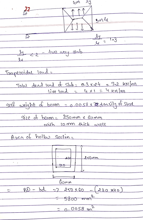
yane ttps///ms.monash.edu/pluginfile.php/7720227/mod resource/content/1/Topic%207 Practice%20exam%20type % 20questions pdf t ENG1001-Lighter,... SI System ENG1001-Week 0f com- Artic Clayton Campus- R.. Unit Guide Managen Current students applying the appropriate load factors Draw a diagram showing how this loadings act on the beam Concrete slab Ducts of diameter 100 mm 4 m 3 m Live load 4 kPa 300 mm 250 mm S m Steel rectangular hollow section beam with 10 mm thick walls 250 mm 60 mm Figure Q1 936953 png
Clayton Campus R.. Unit Guide Manager Current students-.. IENG1001-Lighter... SI System I k 250 mm 8 m Steel rectangular hollow section beam with 10 mm thick walls 250 mm 60 mm Figure Q1 (e) Calculate the corresponding deflection at the mid-span of one beam, using the useful information provided in the next page and the SLS loading calculated in Part (b). Check whether the beam meets the serviceability limit state requirements, based on a maximum beam deflection limit of span/250 936953.png de
monash.edu/pluginfile php/7720227/mod resource/content/1/Topic%207 Practice% 20esam%20type%20questions pd Clayton Campus-R Unit Guide Manager Current students I ING1001-Lighter SI System I ENG1001Wk ENG1001:Topic 7 Exam Practice type Questions 2018 Useful Information for deflection () calculations SwL ymid-span 768E L/2 L/2 SwL ymid-span 384EI L (b) 936953 png
Homework Answers


Add Answer to:
Clayton Campus- R... Unit Guide Manager Current students- ENG1001-Lighter.. SISys NGT001 Q1: Ans: I113.5...
A small footbridge is to have an effective span of 6.0 m and is envisaged to consist of two UB se...
 A small footbridge is to have an effective span of 6.0 m and is envisaged to consist of two UB sections supporting a 180 mm concrete slab with a width of 2.0 m. Determine the BMD and SFD for each beam. Include the self-weight in your calculations. concrete slab 180 mm 6200 (effective span 6000) 2000 UB to have stiffener plates at end to prevent torsion Data: design live load 4.5 kPa deflection limit L/360 steel grade- 300 MPa stiffeners...
5. Determine the mid-span short-term deflection of a simply supported beam with the section shown in...
 5. Determine the mid-span short-term deflection of a simply supported beam with the section shown in Figure Q5. Design data: Concrete strength: fcu 30 MPa. Area of tensile steel reinforcement: As 1500 mm Area of compressive steel reinforcement: A,-1500 mm2 Instantaneous static modulus of elasticity of concrete = 25GPa. Span -8.0 m Loading: Dead load 5.0 kN/m (uniformly distributed load); Live load 5.0 kN/m (uniformly distributed load) (Hint: the height of neutral axis of the mid-span section under the service...
Q1 A cantilever steel beam of length L = 7.5 m carries both a uniformly distributed...
 Q1 A cantilever steel beam of length L = 7.5 m carries both a uniformly distributed load w of 20 kN/m throughout its length and a point load P of 10 kN at its free end, as shown in Figure Q1 (a). The beam is made from a rectangular hollow box section with a width of 300 mm and a depth of 450 mm (refer to Figure Q1 (b)). The wall thickness of the box section is constant throughout which...
Q1. A continuous one-way slab is subjected to Gu(including self-weight) - 7.0 kN/m' Q-4.5 kN/m2. At the exterior ends, the slab is cast monolithically with the edge beams. Assume C30/37 concrete,...
 Q1. A continuous one-way slab is subjected to Gu(including self-weight) - 7.0 kN/m' Q-4.5 kN/m2. At the exterior ends, the slab is cast monolithically with the edge beams. Assume C30/37 concrete, grade 500 steel, and 25-mm cover to bars. Size of each beam is 350mm x 450mm, size of each column is 400mm x 400mm. (a) Determine the slab thickness. (b) Check whether the design shears and moments at critical sections (e.g. at mid- spans and supports) can be determined...
A reinforced concrete cantilevered beam with a span of 5 m extends from the wall, as shown in the...
 A reinforced concrete cantilevered beam with a span of 5 m extends from the wall, as shown in the figure below. The beam has a rectangular cross-section and supports a uniform dead load (DL) of 15 kN/m (excluding the self-weight) and a uniform live load (LL) of 25 kN/m. The beam width is restricted to 400 mm. Use 10M stirrups and 25M bars for tension steel. The maximum aggregate size is 20 mm. 1ie 5.5. beam is located in the...
Q1. A two-storey building is braced against the horizontal load in both directions. The column for the second storey is shown in Fig. Q1. The floor-to-floor height for each storey is 3.5 m. Each beam...
 Q1. A two-storey building is braced against the horizontal load in both directions. The column for the second storey is shown in Fig. Q1. The floor-to-floor height for each storey is 3.5 m. Each beam connected to the column is 5 m long. The sizes of beam A and beam B are 250 x 400 and 300 x 500 mm respectively. The design axial load is 2000 kN. The design end moments about the major axis, which cause the column...
Problem 3: One way solid slab (10 pts) The slab shown in Figure 2 is 200...
 Problem 3: One way solid slab (10 pts) The slab shown in Figure 2 is 200 mm thick. All beams/girders have 400 x 600 mm sections. All columns have 400 x 400 mm sections. Superimposed dead load = 3 kN/m, live load = 4 kN/mº. No walls used. a) Check the slab thickness for deflection control. b) Determine the ultimate uniform load on a l-m wide typical slab strip. c) Determine the ultimate uniform load transferred to beam 2. d)...
PROBLEM Authorities of the Atherton Tablelands in North Queensland proposes a glass covered 3m long walkway scenic lookout to cater for tourists. The glass panels are to be attached to an aluminium f...
 PROBLEM Authorities of the Atherton Tablelands in North Queensland proposes a glass covered 3m long walkway scenic lookout to cater for tourists. The glass panels are to be attached to an aluminium frame attached to a reinforced concrete beam. You are required to design the reinforced concrete beam Gla Safety post up Thick glas SIDE VIEW FRONT VIEW Figure 1. Schematic View of the Walkway Structure To hold the aluminium frame/glass panels and to allow the tourists to walk in...
The following figure 1(a) shows a part of a reinforced concrete building in a school. The...
 The following figure 1(a) shows a part of a reinforced concrete building in a school. The structure consists of precast concrete hollow slabs that rests on the 10.8m long two reinforced concrete beams. The beams are supported on reinforced concrete columns. It is given that, on the top surface of the hollow slab, there will be a concrete screed with 50 mm thickness (assume density of concrete screed is 25 kN/m). In addition, there will be tiles that weigh 0.05...
 A small footbridge is to have an effective span of 6.0 m and is envisaged to consist of two UB sections supporting a 180 mm concrete slab with a width of 2.0 m. Determine the BMD and SFD for each beam. Include the self-weight in your calculations. concrete slab 180 mm 6200 (effective span 6000) 2000 UB to have stiffener plates at end to prevent torsion Data: design live load 4.5 kPa deflection limit L/360 steel grade- 300 MPa stiffeners...
 A small footbridge is to have an effective span of 6.0 m and is envisaged to consist of two UB sections supporting a 180 mm concrete slab with a width of 2.0 m. Determine the BMD and SFD for each beam. Include the self-weight in your calculations. concrete slab 180 mm 6200 (effective span 6000) 2000 UB to have stiffener plates at end to prevent torsion Data: design live load 4.5 kPa deflection limit L/360 steel grade- 300 MPa stiffeners...
 5. Determine the mid-span short-term deflection of a simply supported beam with the section shown in Figure Q5. Design data: Concrete strength: fcu 30 MPa. Area of tensile steel reinforcement: As 1500 mm Area of compressive steel reinforcement: A,-1500 mm2 Instantaneous static modulus of elasticity of concrete = 25GPa. Span -8.0 m Loading: Dead load 5.0 kN/m (uniformly distributed load); Live load 5.0 kN/m (uniformly distributed load) (Hint: the height of neutral axis of the mid-span section under the service...
 Q1 A cantilever steel beam of length L = 7.5 m carries both a uniformly distributed load w of 20 kN/m throughout its length and a point load P of 10 kN at its free end, as shown in Figure Q1 (a). The beam is made from a rectangular hollow box section with a width of 300 mm and a depth of 450 mm (refer to Figure Q1 (b)). The wall thickness of the box section is constant throughout which...
 Q1. A continuous one-way slab is subjected to Gu(including self-weight) - 7.0 kN/m' Q-4.5 kN/m2. At the exterior ends, the slab is cast monolithically with the edge beams. Assume C30/37 concrete, grade 500 steel, and 25-mm cover to bars. Size of each beam is 350mm x 450mm, size of each column is 400mm x 400mm. (a) Determine the slab thickness. (b) Check whether the design shears and moments at critical sections (e.g. at mid- spans and supports) can be determined...
 A reinforced concrete cantilevered beam with a span of 5 m extends from the wall, as shown in the figure below. The beam has a rectangular cross-section and supports a uniform dead load (DL) of 15 kN/m (excluding the self-weight) and a uniform live load (LL) of 25 kN/m. The beam width is restricted to 400 mm. Use 10M stirrups and 25M bars for tension steel. The maximum aggregate size is 20 mm. 1ie 5.5. beam is located in the...
 Q1. A two-storey building is braced against the horizontal load in both directions. The column for the second storey is shown in Fig. Q1. The floor-to-floor height for each storey is 3.5 m. Each beam connected to the column is 5 m long. The sizes of beam A and beam B are 250 x 400 and 300 x 500 mm respectively. The design axial load is 2000 kN. The design end moments about the major axis, which cause the column...
 Problem 3: One way solid slab (10 pts) The slab shown in Figure 2 is 200 mm thick. All beams/girders have 400 x 600 mm sections. All columns have 400 x 400 mm sections. Superimposed dead load = 3 kN/m, live load = 4 kN/mº. No walls used. a) Check the slab thickness for deflection control. b) Determine the ultimate uniform load on a l-m wide typical slab strip. c) Determine the ultimate uniform load transferred to beam 2. d)...
 PROBLEM Authorities of the Atherton Tablelands in North Queensland proposes a glass covered 3m long walkway scenic lookout to cater for tourists. The glass panels are to be attached to an aluminium frame attached to a reinforced concrete beam. You are required to design the reinforced concrete beam Gla Safety post up Thick glas SIDE VIEW FRONT VIEW Figure 1. Schematic View of the Walkway Structure To hold the aluminium frame/glass panels and to allow the tourists to walk in...
 The following figure 1(a) shows a part of a reinforced concrete building in a school. The structure consists of precast concrete hollow slabs that rests on the 10.8m long two reinforced concrete beams. The beams are supported on reinforced concrete columns. It is given that, on the top surface of the hollow slab, there will be a concrete screed with 50 mm thickness (assume density of concrete screed is 25 kN/m). In addition, there will be tiles that weigh 0.05...
Most questions answered within 3 hours.
-
A .15kg rubber ball is bounced off a wall. Before hitting the
wall, the ball moves...
asked 10 minutes ago -
A manufacturing company preparing to build a new plant is
considering three potential locations for it....
asked 11 minutes ago -
B. If compound Y has approximately the same values of solubility
in toluene as compound X,...
asked 58 minutes ago -
Oscar Inc. has inventory in Japan valued at 39,051,000 Yen one
year ago. One year ago...
asked 1 hour ago -
If Canada suffered from "fundamental disequilibrium," and its
government choose not to devalue its currency, a...
asked 1 hour ago -
4. How many input & output Key Value Pairs are passed into,
and emitted out of...
asked 1 hour ago -
Why would your heart not function well if constructed of
skeletal muscle? What is the particular...
asked 1 hour ago -
Please respond to this essay question in full essay form for
Chemistry 1102 Organic and Biochemistry:...
asked 1 hour ago -
Determine the head loss and velocity of flow in a water supply main
of 15.0 cm...
asked 1 hour ago -
A marketing executive who knowingly authorizes a shoddy
defective product to be brought to market is...
asked 1 hour ago -
Write a psudocode:
1. Define a function called authorize that takes in 2 strings,
uName, and...
asked 1 hour ago -
What Hall voltage (in mV) is produced by a 0.180 T field applied
across a 2.60...
asked 1 hour ago