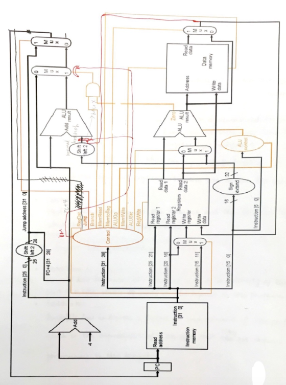
![5. (35 points) We wish to add the single cycle datapath and control. Add an a new instruction im Gump memory) to page. This necessary datapaths and control signals to the attached figure on next new jump instruction bm SI, S2, 100 writes PC with the value in memory location 0, i.e., PC (next PC)+memory [$2-100]. The format is the same as lw except that ri field is not used. Give control values of all the control lines for jm. Add more control lines if necessary RegDst Jump Branch MemRead T MemtoRe Reg Write ALUo Mem Write ALUSrc](http://img.homeworklib.com/questions/3131a410-cfac-11ea-b698-15b2fa593e6c.png?x-oss-process=image/resize,w_560)
The answer to the table given by teacher is:
RegDst-0
Jump-x
Branch-1
MemRead-1
MemtoReg-x
ALUop-1
MemWrite-x
ALUSrc-1 (not sure about this one, please give your answer)
RegWrite-x
x means the signal cannot be set in this instruction.
Could you explain the answer in details?
Homework Answers
In the image, for jump instruction address provided as jump
address[31 0].
This states destination register is 0
So RegDst-0
-------------------------------------------------------------------------------------
Jump register value will be depend on label or branch. Hence it may
have any value.
So Jump - x
------------------------------------------------------------------------------------------
Branch -> 1
Activating the branch register to 1 to allow execute jmp
instruction.
---------------------------------------------------------------------------------
MemRead -> 1
To jump from one branch to next branch, so need to write the data
from one brach to
next branch. So activate MemRead register to 1.
---------------------------------------------------------------------------------------
ALUop -> 1
This says the alu operations carry on while executing jmp
instruction.
----------------------------------------------------------------------------------------
MemWrite
Writing into memory is depend on instructions. So it may be any
value. Hence it is x. (no-operation)
---------------------------------------------------------------------------------------------
ALUSrc - 1
Yes, it is correct since logical operations need to be done.
-----------------------------------------------------------------------------------
RegWrite -> x
Only reading is required not Regwrite, so no operation.
Add Answer to:
The answer to the table given by teacher is:
RegDst-0
Jump-x
Branch-1
MemRead-1
MemtoReg-x
ALUop-1
MemWrite-x...
*For a clearer view of the datapath* Answer choices for all Consider the MIPS single cycle...
 *For a clearer view of the datapath*
Answer choices for all
Consider the MIPS single cycle datapath shown below. Select the correct control signals that will be generated by the control unit for the following instruction: andi $t0,$t1,4 Instruction (25-01 Shin Jump address (31-0) - left 2) 28 PC +4 [31-28) XCS result left 2 RegDst Jump Branch MemRead Instruction (31-26] MemtoReg Control ALUOP MemWrite ALUSrc RegWrite Instruction (25-21] PC Read address Read register 1 Read Instruction (20-16] Read data...
*For a clearer view of the datapath*
Answer choices for all
Consider the MIPS single cycle datapath shown below. Select the correct control signals that will be generated by the control unit for the following instruction: andi $t0,$t1,4 Instruction (25-01 Shin Jump address (31-0) - left 2) 28 PC +4 [31-28) XCS result left 2 RegDst Jump Branch MemRead Instruction (31-26] MemtoReg Control ALUOP MemWrite ALUSrc RegWrite Instruction (25-21] PC Read address Read register 1 Read Instruction (20-16] Read data...
(o x Add Addresult ALU Shift left 2 Regst Branch MemRead Instruction (31-26) MemtoReg Controll ALUOP...
 (o x Add Addresult ALU Shift left 2 Regst Branch MemRead Instruction (31-26) MemtoReg Controll ALUOP MemWrite ALUSC RogWrite Instruction [25-21] Read register 1 Read Instruction (20-16) Read data 1 register 2 Write Read Instruction (15-11) Write data Registers PC Read address Zoro ALU ALU Instruction (31-0) Instruction memory result Address Read data register data 2 **039 -25 Write Data data memory Instruction (15-01 16 Sign- extend ALU control Instruction 15-01 With regards to the single cycle implementation (as shown...
Question 5 0.25 pts What is the value of the MemWrite control signal? Question 6 0.25 pts What is the value of the ALUSrc control signal? Add Add Sum--(1 4 Shift left 1 Branch MemRead Instruction [6-...
 Question 5 0.25 pts What is the value of the MemWrite control signal? Question 6 0.25 pts What is the value of the ALUSrc control signal? Add Add Sum--(1 4 Shift left 1 Branch MemRead Instruction [6-0] ControMemtoReg MemWrite ALUSrc RegWrite Instruction [19-15]Read Read register 1 Read Read data! PCaddress Instruction [24-20] Zero ALU ALU result register 2 Instruction 31-0 Instruction [11-7 Read1 Address data | Write Read register daiaALU | M Instruction memory Write data Registers Write Data data...
Assume that ‘slt $1, $2, $3’ is executed with the implementation in the picture. Identify the value of the 9-bit control...
 Assume that ‘slt $1, $2, $3’ is executed with the implementation
in the picture. Identify the value of the 9-bit control
signals.
Add u X ALU result 4 Add Shift left 2 RegDst Branch MemRead MemtoReg Control ALUOP Instruction [31-26 MemWrite ALUSRC RegWrite Instruction [25-21] Read register 1 Read Read PC address Instruction [20-16] data 1 Read Zero register 2 Instruction ALU ALU 31-0] Instruction memory Read data M Read Address Write result u M Instruction [15-11] register data 2...
Assume that ‘slt $1, $2, $3’ is executed with the implementation
in the picture. Identify the value of the 9-bit control
signals.
Add u X ALU result 4 Add Shift left 2 RegDst Branch MemRead MemtoReg Control ALUOP Instruction [31-26 MemWrite ALUSRC RegWrite Instruction [25-21] Read register 1 Read Read PC address Instruction [20-16] data 1 Read Zero register 2 Instruction ALU ALU 31-0] Instruction memory Read data M Read Address Write result u M Instruction [15-11] register data 2...
6. Consider a datapath similar to the one in figure below, but for a processor that only has one type of instruction: unconditional PC-relative branch. What would the cycle time be for this dat...
 6. Consider a datapath similar to the one in figure below, but for a processor that only has one type of instruction: unconditional PC-relative branch. What would the cycle time be for this datapath? PCSrc Add ALU Add result Shift +( left 2 Read register 1 ALUSrc, 4 ALU operation PCRead PC-address Read data 1 Registers Read data 2 MemWrite Zero ALU ALU-I Address MemtoReg Instruction register 2 Instruction | Write Read data-M register Write Lu memory Write Data data...
How would the multicycle MIPS design support the jr instruction? Show the machine code format and...
 How would the multicycle MIPS design support the jr instruction?
Show the machine code format and your solution should describe any
new datapath features and control changes to the finite-state
diagram below (this may include adding new states).
Information for problem1 0 Instruction Fetch 1 Decode/Register Fetch 2 Address Calculation 3 Memory Read 4 Write-back Step 5 Memory Write 6 R-execution 7 R-completion 8 Branch completion 9 Jump completion O Mem Read ALUSelA 0 ALUSelB 01 lorD 0 ALUOp 00...
How would the multicycle MIPS design support the jr instruction?
Show the machine code format and your solution should describe any
new datapath features and control changes to the finite-state
diagram below (this may include adding new states).
Information for problem1 0 Instruction Fetch 1 Decode/Register Fetch 2 Address Calculation 3 Memory Read 4 Write-back Step 5 Memory Write 6 R-execution 7 R-completion 8 Branch completion 9 Jump completion O Mem Read ALUSelA 0 ALUSelB 01 lorD 0 ALUOp 00...
MCS) Add Addresult ALU Shift left 2 RegDst Branch MemRead MemtoReg Instruction (31-26] Control ALUOP MemWrite...
 MCS) Add Addresult ALU Shift left 2 RegDst Branch MemRead MemtoReg Instruction (31-26] Control ALUOP MemWrite ALUS RegWrite PC instruction (25-21] Instruction (20-16) Read address Instruction (31-0) Instruction memory Read register 1 Read Read data 1 register 2 Write Read Zoro ALU ALU result Address Read data instruction (15-11] register data 2 x3) Write data Registers Write Data data memory Instruction 15-01 16 Sign- extend ALU control Instruction (5-0) With regards to the single cycle implementation (as shown in the...
Question 4: Single Cycle Datapath Control (15 points) We wish to add the hardware support for...
 Question 4: Single Cycle Datapath Control (15 points) We wish to add the hardware support for a special R-type instruction jlr Jump and Link Register) to the single-cycle datapath below. Though this is an R-type instruction, but it is a special one that has the opcode being 000001 (instead of 000000), so the control unit will be able to differentiate this jlr instruction from the other R-type instructions and generate a special set of controls for this instruction. Opcode rs...
it is the same question A block diagram of MIPS architecture is given below. What is...
 it is the same question
A block diagram of MIPS architecture is given below. What is the value of the control bit for each MUX during the execution of the given instruction? Note, you may use N/Aif MUX output is not usefu Add MUX 4 ALU Add, result Shift left 2 RegDst Branch MemRead Instruction (31-26] Control Memto Reg ALUOP Mem Write ALUSrc RegWrite Instruction [25-21) PC Read address Instruction (20-16] MUXT Read register 1 Read Read data 1 register...
it is the same question
A block diagram of MIPS architecture is given below. What is the value of the control bit for each MUX during the execution of the given instruction? Note, you may use N/Aif MUX output is not usefu Add MUX 4 ALU Add, result Shift left 2 RegDst Branch MemRead Instruction (31-26] Control Memto Reg ALUOP Mem Write ALUSrc RegWrite Instruction [25-21) PC Read address Instruction (20-16] MUXT Read register 1 Read Read data 1 register...
Q4: Answer the following questions. [7 Marks] The single cycle implementation of MIPS is as shown...
 Q4: Answer the following questions. [7 Marks] The single cycle implementation of MIPS is as shown below. Answer the following questions with reference to "beq $S1, $S2, 8H” instruction. Assume that the contents of the registers S1 = 10 H, S2 = 10H, and PC = 16H, pointing to the instruction under consideration. 1. What is the addressing mode of the instruction? [1] ii. Which part of the instruction format, address of S1 and S2 are stored? [1] 111. What...
 *For a clearer view of the datapath*
Answer choices for all
Consider the MIPS single cycle datapath shown below. Select the correct control signals that will be generated by the control unit for the following instruction: andi $t0,$t1,4 Instruction (25-01 Shin Jump address (31-0) - left 2) 28 PC +4 [31-28) XCS result left 2 RegDst Jump Branch MemRead Instruction (31-26] MemtoReg Control ALUOP MemWrite ALUSrc RegWrite Instruction (25-21] PC Read address Read register 1 Read Instruction (20-16] Read data...
*For a clearer view of the datapath*
Answer choices for all
Consider the MIPS single cycle datapath shown below. Select the correct control signals that will be generated by the control unit for the following instruction: andi $t0,$t1,4 Instruction (25-01 Shin Jump address (31-0) - left 2) 28 PC +4 [31-28) XCS result left 2 RegDst Jump Branch MemRead Instruction (31-26] MemtoReg Control ALUOP MemWrite ALUSrc RegWrite Instruction (25-21] PC Read address Read register 1 Read Instruction (20-16] Read data...
 (o x Add Addresult ALU Shift left 2 Regst Branch MemRead Instruction (31-26) MemtoReg Controll ALUOP MemWrite ALUSC RogWrite Instruction [25-21] Read register 1 Read Instruction (20-16) Read data 1 register 2 Write Read Instruction (15-11) Write data Registers PC Read address Zoro ALU ALU Instruction (31-0) Instruction memory result Address Read data register data 2 **039 -25 Write Data data memory Instruction (15-01 16 Sign- extend ALU control Instruction 15-01 With regards to the single cycle implementation (as shown...
 Question 5 0.25 pts What is the value of the MemWrite control signal? Question 6 0.25 pts What is the value of the ALUSrc control signal? Add Add Sum--(1 4 Shift left 1 Branch MemRead Instruction [6-0] ControMemtoReg MemWrite ALUSrc RegWrite Instruction [19-15]Read Read register 1 Read Read data! PCaddress Instruction [24-20] Zero ALU ALU result register 2 Instruction 31-0 Instruction [11-7 Read1 Address data | Write Read register daiaALU | M Instruction memory Write data Registers Write Data data...
 Assume that ‘slt $1, $2, $3’ is executed with the implementation
in the picture. Identify the value of the 9-bit control
signals.
Add u X ALU result 4 Add Shift left 2 RegDst Branch MemRead MemtoReg Control ALUOP Instruction [31-26 MemWrite ALUSRC RegWrite Instruction [25-21] Read register 1 Read Read PC address Instruction [20-16] data 1 Read Zero register 2 Instruction ALU ALU 31-0] Instruction memory Read data M Read Address Write result u M Instruction [15-11] register data 2...
Assume that ‘slt $1, $2, $3’ is executed with the implementation
in the picture. Identify the value of the 9-bit control
signals.
Add u X ALU result 4 Add Shift left 2 RegDst Branch MemRead MemtoReg Control ALUOP Instruction [31-26 MemWrite ALUSRC RegWrite Instruction [25-21] Read register 1 Read Read PC address Instruction [20-16] data 1 Read Zero register 2 Instruction ALU ALU 31-0] Instruction memory Read data M Read Address Write result u M Instruction [15-11] register data 2...
 6. Consider a datapath similar to the one in figure below, but for a processor that only has one type of instruction: unconditional PC-relative branch. What would the cycle time be for this datapath? PCSrc Add ALU Add result Shift +( left 2 Read register 1 ALUSrc, 4 ALU operation PCRead PC-address Read data 1 Registers Read data 2 MemWrite Zero ALU ALU-I Address MemtoReg Instruction register 2 Instruction | Write Read data-M register Write Lu memory Write Data data...
 How would the multicycle MIPS design support the jr instruction?
Show the machine code format and your solution should describe any
new datapath features and control changes to the finite-state
diagram below (this may include adding new states).
Information for problem1 0 Instruction Fetch 1 Decode/Register Fetch 2 Address Calculation 3 Memory Read 4 Write-back Step 5 Memory Write 6 R-execution 7 R-completion 8 Branch completion 9 Jump completion O Mem Read ALUSelA 0 ALUSelB 01 lorD 0 ALUOp 00...
How would the multicycle MIPS design support the jr instruction?
Show the machine code format and your solution should describe any
new datapath features and control changes to the finite-state
diagram below (this may include adding new states).
Information for problem1 0 Instruction Fetch 1 Decode/Register Fetch 2 Address Calculation 3 Memory Read 4 Write-back Step 5 Memory Write 6 R-execution 7 R-completion 8 Branch completion 9 Jump completion O Mem Read ALUSelA 0 ALUSelB 01 lorD 0 ALUOp 00...
 MCS) Add Addresult ALU Shift left 2 RegDst Branch MemRead MemtoReg Instruction (31-26] Control ALUOP MemWrite ALUS RegWrite PC instruction (25-21] Instruction (20-16) Read address Instruction (31-0) Instruction memory Read register 1 Read Read data 1 register 2 Write Read Zoro ALU ALU result Address Read data instruction (15-11] register data 2 x3) Write data Registers Write Data data memory Instruction 15-01 16 Sign- extend ALU control Instruction (5-0) With regards to the single cycle implementation (as shown in the...
 Question 4: Single Cycle Datapath Control (15 points) We wish to add the hardware support for a special R-type instruction jlr Jump and Link Register) to the single-cycle datapath below. Though this is an R-type instruction, but it is a special one that has the opcode being 000001 (instead of 000000), so the control unit will be able to differentiate this jlr instruction from the other R-type instructions and generate a special set of controls for this instruction. Opcode rs...
 it is the same question
A block diagram of MIPS architecture is given below. What is the value of the control bit for each MUX during the execution of the given instruction? Note, you may use N/Aif MUX output is not usefu Add MUX 4 ALU Add, result Shift left 2 RegDst Branch MemRead Instruction (31-26] Control Memto Reg ALUOP Mem Write ALUSrc RegWrite Instruction [25-21) PC Read address Instruction (20-16] MUXT Read register 1 Read Read data 1 register...
it is the same question
A block diagram of MIPS architecture is given below. What is the value of the control bit for each MUX during the execution of the given instruction? Note, you may use N/Aif MUX output is not usefu Add MUX 4 ALU Add, result Shift left 2 RegDst Branch MemRead Instruction (31-26] Control Memto Reg ALUOP Mem Write ALUSrc RegWrite Instruction [25-21) PC Read address Instruction (20-16] MUXT Read register 1 Read Read data 1 register...
 Q4: Answer the following questions. [7 Marks] The single cycle implementation of MIPS is as shown below. Answer the following questions with reference to "beq $S1, $S2, 8H” instruction. Assume that the contents of the registers S1 = 10 H, S2 = 10H, and PC = 16H, pointing to the instruction under consideration. 1. What is the addressing mode of the instruction? [1] ii. Which part of the instruction format, address of S1 and S2 are stored? [1] 111. What...
Most questions answered within 3 hours.
-
Suppose you are the money manager of a $4.74 million investment
fund. The fund consists of...
asked 32 seconds from now -
What is a highly unreasonable omission or misrepresentation
involving an extreme departure from the standards of...
asked 22 minutes ago -
What are the three mechanisms that control hormone release and a
example of each.
asked 36 minutes ago -
What would happen to the price level and real GDP if new, large
reserves of petroleum...
asked 38 minutes ago -
2. According to economists, people pollute because
a. They have low self esteem
b. They are...
asked 31 minutes ago -
For this project you will be writing up a simple Clock program
to keep track of...
asked 38 minutes ago -
The December 31, 2018, adjusted trial balance for Fightin' Blue
Hens Corporation is presented below.
...
asked 42 minutes ago -
E21-11 (L02) (Amortization Schedule and Journal Entries for
Lessee) Laura Leasing Company signs an agreement on...
asked 1 hour ago -
Joe Mataya’s company provides after-sales support for all the
photo-copiers and high-load printers on our campus....
asked 1 hour ago -
In a statistics class there are 12 students. Five of the
students are seniors and the...
asked 1 hour ago -
can someone please explain for me in any easy way what does
Dipole mean ?
asked 1 hour ago -
Consider the following grammar:
<S> → <A> a <B> b
<A> → <A> b | b...
asked 1 hour ago