Design (and then verify your design by simulating it) a two-bit
counter that counts up or down. Use an enable input E to determine
whether the counter is on or off: if E = 0 the counter is disabled
and remains at its present count even if clock pulses are applied.
If E = 1, the counter is enabled and a second input, x, determines
the direction of the count: if x = 1 the circuit counts upward 00,
01, 10, 11, repeat; if x = 0 the circuit counts downward 11, 10,
01, 00, repeat. So, design the circuit with E and x as inputs. Test
in verilog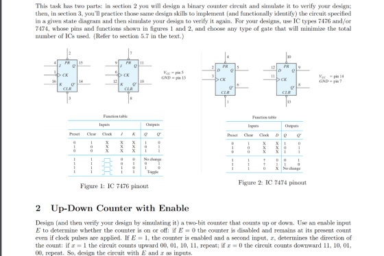
Homework Answers


Add Answer to:
Design (and then verify your design by simulating it) a two-bit
counter that counts up or...
Up-Down counter with enable using JK flip-flops: Design, construct and test a 2-bit counter that counts up or down.
Up-Down counter with enable using JK flip-flops: Design, construct and test a 2-bit counter that counts up or down. An enable input E determines whether the counter is on or off. If E = 0, the counter is disabled and remains in the present count even though clock pulses are applied to the flip-flops. If E= 1, the counter in enabled and a second input, x, determines the count direction. If x= 1, the circuit counts up with the sequence...
5. (7 points) Shown in the following block diagram is a 4-bit up-counter with parallel load, clk ...
 5. (7 points) Shown in the following block diagram is a 4-bit up-counter with parallel load, clk Dc BA load clr where clr and load are asynchronous inputsi.e., one of the following operations will be performed “simultaneously" (independently of the clock) when the inputs change values: clr load operations 1 X clear 0 0parallel load 1 up-counting 0 the above block diagram and any logic gates you want to build an offset down-counter to count from QpQcQBQA 0111 0110010 ....
ercise 5 Part One: Sequential Logic ask 5.1,1: Design a 4-bit up/down counter that does not...
 ercise 5 Part One: Sequential Logic ask 5.1,1: Design a 4-bit up/down counter that does not overflow or underflow. That is, counting up is disabled when it reaches its maximum value and counting down is disabled when it reaches its minimum value. Use circuit simulation to verify your design. Task 5.1.2: Design a logic implementation of the Finite State Machine in Fiqure 2.3 using JK flip flops. It can be assumed that unused state combinations may be considered as don't...
6. Show how to connect a 74HC93 4-bit asynchronous counter for each of the following moduli:...
 6. Show how to connect a 74HC93 4-bit asynchronous counter for each of the following moduli: (a) 9 (b) 11 (c) 13 (d) 14 (e) 15 10. The waveforms in Figure 9-69 are applied to the count enable, clear, and clock inputs as indi- cated. Show the counter output waveforms in proper relation to these inputs. The clear input is asynchronous. CTEN CTENCTR DIV 16 CLR
Design a three-bit counter using D flip-flops that has the following characteristics: When the value of...
 Design a three-bit counter using D flip-flops that has the following characteristics: When the value of an input x is 0, the counter counts "down" in standard order. When the value of x is 1, the counter counts "up" in standard order a. First, complete the state table shown below Present State Next State Excitation 0 0 0 0 0 0 1 0 0 0 0 0 0 b. Next, derive the logic equations using the Karnaugh maps shown below...
2. Obtain the schematic for Variant D of the counter above operating with two additional modes: p...
 2. Obtain the schematic for Variant D of the counter above operating with two additional modes: parallel load of initial state and enable. The parallel load and enable modes are controlled by inputs L and E. The state is loaded synchronously with clock with L-1, E-1, counts as shown in problem 1 with L=0, E-1 otherwise the state does not change. Obtain the schematic, one can use any multiplexers. X-0 IN江 01 10 X-1 X-1 X-1 x=1
2. Obtain the...
2. Obtain the schematic for Variant D of the counter above operating with two additional modes: parallel load of initial state and enable. The parallel load and enable modes are controlled by inputs L and E. The state is loaded synchronously with clock with L-1, E-1, counts as shown in problem 1 with L=0, E-1 otherwise the state does not change. Obtain the schematic, one can use any multiplexers. X-0 IN江 01 10 X-1 X-1 X-1 x=1
2. Obtain the...
Design a two-bit up/down binary counter using D flip-flops that can count in binary from 0 to 7.
Design a two-bit up/down binary counter using D flip-flops that can count in binary from 0 to 7. When the control input x is 0, the circuit counts down, and when it is 1, the circuit counts up. (a) Obtain the state table of the two-bit counter. (b) Obtain the state diagram (c) Draw the logic diagram of the circuit.
1. Build the 4-bit synchronous count up counter (using two 74109 Dual J-K F.F and 74LS08...
 1. Build the 4-bit synchronous count up counter (using two 74109 Dual J-K F.F and 74LS08 AND IC) shown in Figure 5. LOLLSB) L3(M58) 74L SOBD 74LS08D 2. Put the PR on "1" and CLR on "O" to initialize the counter, then put the CLR on "1"and complete the following table. Clock # L3 L2 L1 LO Decimal Value (L3 L2 L1 LO) lorbluffen 14 15 16 17 3. Compare the outputs in this table with the outputs in Part...
Please show process and I will rate faster!!! 2. Design a two-bit up/down binary counter using...
 Please show process and I will rate faster!!!
2. Design a two-bit up/down binary counter using T-fip-flops that can count in binary from 0 to 3. When the control input x is 0, the circuit counts up and when it is 1, the circuit counts down. (a) Obtain the state table of the two-bit counter (P. S., Input, N. S., Output). (b) Obtain the state diagram. (c) Draw the logic diagram of the circuit.
Please show process and I will rate faster!!!
2. Design a two-bit up/down binary counter using T-fip-flops that can count in binary from 0 to 3. When the control input x is 0, the circuit counts up and when it is 1, the circuit counts down. (a) Obtain the state table of the two-bit counter (P. S., Input, N. S., Output). (b) Obtain the state diagram. (c) Draw the logic diagram of the circuit.
1. Suppose you want to design a 2-bit binary up-counter. Construct the state table using A1...
 1. Suppose you want to design a 2-bit binary up-counter. Construct the state table using A1 and AO as the previous state of bits and A1+, A0+ as the next bit states, ie, to count from 00 to 01, A1 stays at 0, but AO changes from 0 to 1. Let the counter wrap-around, such that 11 -> 00. Draw the state diagram. 2. Next, add in a third input, En, for enable. The counter can only count up when...
 5. (7 points) Shown in the following block diagram is a 4-bit up-counter with parallel load, clk Dc BA load clr where clr and load are asynchronous inputsi.e., one of the following operations will be performed “simultaneously" (independently of the clock) when the inputs change values: clr load operations 1 X clear 0 0parallel load 1 up-counting 0 the above block diagram and any logic gates you want to build an offset down-counter to count from QpQcQBQA 0111 0110010 ....
 ercise 5 Part One: Sequential Logic ask 5.1,1: Design a 4-bit up/down counter that does not overflow or underflow. That is, counting up is disabled when it reaches its maximum value and counting down is disabled when it reaches its minimum value. Use circuit simulation to verify your design. Task 5.1.2: Design a logic implementation of the Finite State Machine in Fiqure 2.3 using JK flip flops. It can be assumed that unused state combinations may be considered as don't...
 6. Show how to connect a 74HC93 4-bit asynchronous counter for each of the following moduli: (a) 9 (b) 11 (c) 13 (d) 14 (e) 15 10. The waveforms in Figure 9-69 are applied to the count enable, clear, and clock inputs as indi- cated. Show the counter output waveforms in proper relation to these inputs. The clear input is asynchronous. CTEN CTENCTR DIV 16 CLR
 Design a three-bit counter using D flip-flops that has the following characteristics: When the value of an input x is 0, the counter counts "down" in standard order. When the value of x is 1, the counter counts "up" in standard order a. First, complete the state table shown below Present State Next State Excitation 0 0 0 0 0 0 1 0 0 0 0 0 0 b. Next, derive the logic equations using the Karnaugh maps shown below...
 2. Obtain the schematic for Variant D of the counter above operating with two additional modes: parallel load of initial state and enable. The parallel load and enable modes are controlled by inputs L and E. The state is loaded synchronously with clock with L-1, E-1, counts as shown in problem 1 with L=0, E-1 otherwise the state does not change. Obtain the schematic, one can use any multiplexers. X-0 IN江 01 10 X-1 X-1 X-1 x=1
2. Obtain the...
2. Obtain the schematic for Variant D of the counter above operating with two additional modes: parallel load of initial state and enable. The parallel load and enable modes are controlled by inputs L and E. The state is loaded synchronously with clock with L-1, E-1, counts as shown in problem 1 with L=0, E-1 otherwise the state does not change. Obtain the schematic, one can use any multiplexers. X-0 IN江 01 10 X-1 X-1 X-1 x=1
2. Obtain the...
 1. Build the 4-bit synchronous count up counter (using two 74109 Dual J-K F.F and 74LS08 AND IC) shown in Figure 5. LOLLSB) L3(M58) 74L SOBD 74LS08D 2. Put the PR on "1" and CLR on "O" to initialize the counter, then put the CLR on "1"and complete the following table. Clock # L3 L2 L1 LO Decimal Value (L3 L2 L1 LO) lorbluffen 14 15 16 17 3. Compare the outputs in this table with the outputs in Part...
 Please show process and I will rate faster!!!
2. Design a two-bit up/down binary counter using T-fip-flops that can count in binary from 0 to 3. When the control input x is 0, the circuit counts up and when it is 1, the circuit counts down. (a) Obtain the state table of the two-bit counter (P. S., Input, N. S., Output). (b) Obtain the state diagram. (c) Draw the logic diagram of the circuit.
Please show process and I will rate faster!!!
2. Design a two-bit up/down binary counter using T-fip-flops that can count in binary from 0 to 3. When the control input x is 0, the circuit counts up and when it is 1, the circuit counts down. (a) Obtain the state table of the two-bit counter (P. S., Input, N. S., Output). (b) Obtain the state diagram. (c) Draw the logic diagram of the circuit.
 1. Suppose you want to design a 2-bit binary up-counter. Construct the state table using A1 and AO as the previous state of bits and A1+, A0+ as the next bit states, ie, to count from 00 to 01, A1 stays at 0, but AO changes from 0 to 1. Let the counter wrap-around, such that 11 -> 00. Draw the state diagram. 2. Next, add in a third input, En, for enable. The counter can only count up when...
Most questions answered within 3 hours.
-
C++ program c that reads a list of costs for a few items.
Program should calculate...
asked 21 seconds ago -
You are a manager with a company where employees frequently
travel as part of their job....
asked 6 minutes ago -
In this assignment you will implement software for your local
library. The user of the software...
asked 16 minutes ago -
A manufacturer of banana chips would like to know whether its
bag filling machine works correctly...
asked 10 minutes ago -
Weight gain during pregnancy. In 2004, the
state of North Carolina released to the public a...
asked 12 minutes ago -
Write an abstract class “Student” and three concrete
classes, “UnderGrad” and “Graduate” both inherit from Student...
asked 12 minutes ago -
Create a bottom-up solution to
the minimum
falling path sum problem. By bottom-up, I mean you should not
use...
asked 17 minutes ago -
Suppose that the supply of barley is given by the supply
function : Qs= 500+5p+2r
where...
asked 16 minutes ago -
A chemist dilutes 82.1 ml of 4.07 M sodium chloride to make a
1.7 M solution....
asked 20 minutes ago -
A cell biologist interested in the transport of calcium ions
(Ca2+) across the plasma membrane of...
asked 25 minutes ago -
Suppose the average time it takes to drive from SFSU to Redwood
City is 41 minutes,...
asked 31 minutes ago -
The more formal name for a balance sheet is:
A) statement of net worth
B) statement...
asked 28 minutes ago