Please solve all these questions and give a detailed explanation for your answer. When drawing the bode plots, please make sure that they are hand drawn. Please show in detail how you got them and hopefully all your answers are correct. When drawing the bode plots for the magnitude, the y-axis should be 20log(abs(H(jw))). When drawing the bode plots for the phase, the y-axis should be in degrees. The x-axis for both plots should be "w". Thank you very much for all your help in advanced.

Homework Answers


Add Answer to:
Please solve all these questions and give a detailed explanation
for your answer. When drawing the...
please answer all questions and show all steps 3. Draw the magnitude characteristic of the Bode...
 please answer all questions and show all steps
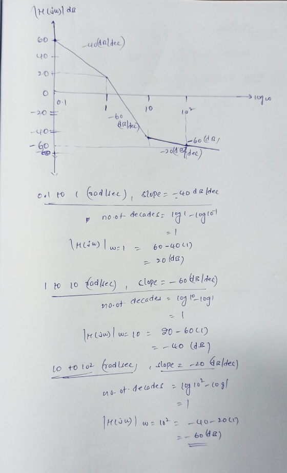
3. Draw the magnitude characteristic of the Bode plot of the following transfer function: Hsout20(0.1s + 1 Vin S(s1)(0.01s +1) a) ldentify the poles and zeros b) Sketch the magnitude plot. The y-axis should be in dB. The x-axis should logarithmic, but labeled in rad/sec. Use MATLAB to draw the complete Bode plot and check your answer. If the input current is uln(t)-2 cos(2t + 30%), what is the output voltage. Use...
please answer all questions and show all steps
3. Draw the magnitude characteristic of the Bode plot of the following transfer function: Hsout20(0.1s + 1 Vin S(s1)(0.01s +1) a) ldentify the poles and zeros b) Sketch the magnitude plot. The y-axis should be in dB. The x-axis should logarithmic, but labeled in rad/sec. Use MATLAB to draw the complete Bode plot and check your answer. If the input current is uln(t)-2 cos(2t + 30%), what is the output voltage. Use...
Can you please solve these problems, and show all work? Please number each part of your answer to identify what problem...
 Can you please solve these problems, and show all work?
Please number each part of your answer to identify what problem
section is being solved.
Please circle your answers.
Please include the MATLAB portion, if you can, please.
Thank you.
Problem 1: Consider the causal CT systems with transfer functions s +1 + 16) Ha(s)-(s+ 10)(s+1) й,(s) H3(s)S+ D) H4(s) S1) (s2 +s16) 1. Write magnitude and phase expressions for their Bode plots and sketch their asymptotes. Verify using MATLAB....
Can you please solve these problems, and show all work?
Please number each part of your answer to identify what problem
section is being solved.
Please circle your answers.
Please include the MATLAB portion, if you can, please.
Thank you.
Problem 1: Consider the causal CT systems with transfer functions s +1 + 16) Ha(s)-(s+ 10)(s+1) й,(s) H3(s)S+ D) H4(s) S1) (s2 +s16) 1. Write magnitude and phase expressions for their Bode plots and sketch their asymptotes. Verify using MATLAB....
a) Please show all your steps. For the magnitude and phase angle plots, approximate bode diagrams...
 a) Please show all your steps. For the magnitude and phase angle plots, approximate bode diagrams (as provided in the last frequency lecture notes) and use MATLAB to obtain the exact solutions. You will observe that the maximum difference in the solutions are at the corner frequencies! b) Upholding Ethical standard is expected from you. If any ethical violation is detected, appropriate academic measure will be applied. c) Please respect the due date too. 250 1. Given: G(S) = 52...
please solve question 5 and 6 and give detailed description if possible . here is the...
 please solve question 5 and 6
and give detailed description if possible .
here is the figure
3.3.3. PRELAB WORK For the circuit shown in Figure 18. (a), assume L 2mH, and C 5nF 1. Calculate fo and the value of R to give a circuit of Q of 5. 2. Calculate the values of f1. f2 and B using Equations (34), (35), (29), and (30) 3, 4. For the same circuit assume L 2mH, C 5nF and R 1002....
please solve question 5 and 6
and give detailed description if possible .
here is the figure
3.3.3. PRELAB WORK For the circuit shown in Figure 18. (a), assume L 2mH, and C 5nF 1. Calculate fo and the value of R to give a circuit of Q of 5. 2. Calculate the values of f1. f2 and B using Equations (34), (35), (29), and (30) 3, 4. For the same circuit assume L 2mH, C 5nF and R 1002....
Please solve these 3 questions and please give me a detailed explanation for your answer. Hopeful...
 Please solve these 3 questions and please give me a detailed
explanation for your answer. Hopefully your answers are correct.
Please help me out because I am stuck on how to solve these
problems for a long time.
4. Which is the solution for a(0, y) = 0, u(1,y) = 0 u(z,0)=2sin(3xx), lim u(z,y)=0? B. 2e-3ry sin(3nx) C. 2sinh(3Ty)sin(3T) D. 2sinh(3Ty) cos(3Tx) E. none of the above 5. If y" + 3y' +2y = δ(t _ 2) with y(0) =...
Please solve these 3 questions and please give me a detailed
explanation for your answer. Hopefully your answers are correct.
Please help me out because I am stuck on how to solve these
problems for a long time.
4. Which is the solution for a(0, y) = 0, u(1,y) = 0 u(z,0)=2sin(3xx), lim u(z,y)=0? B. 2e-3ry sin(3nx) C. 2sinh(3Ty)sin(3T) D. 2sinh(3Ty) cos(3Tx) E. none of the above 5. If y" + 3y' +2y = δ(t _ 2) with y(0) =...
Y(s) C(s) G(s) R(S) Figure 1: Closed-loop system Q2 Consider the setup in Figure 1 with S s1 (i) ...
 Y(s) C(s) G(s) R(S) Figure 1: Closed-loop system Q2 Consider the setup in Figure 1 with S s1 (i) Design a K,τ, α in the lead compensator 1TOS so that the closed-loop system shown in Figure 1 has a steady state error of.0 for a unit ramp reference input at R and a phase margin of about 45 degrees K, α, τ without Bode plots. When you add phase with the lead compensator add an additional 10 degrees of phase....
Please show all work and answer all the questions so I can learn how to do it on my own. Thank yo...
 Please show all work and answer all the questions so I can learn
how to do it on my own. Thank you in advance.
(GM,PM,wcg,wepl-margin(sys) computes the gain margin GM, the phase margin PM, and the associated frequencies weg and wep. They can also be read from the Bode plot. G(s) R(s) EX G(s)- (s +10(s+1)2 Questions Draw the Bode plot when K-1, find the gain margin, and determine the closed-loop stability. (b) Convert the gain margin to a normal...
Please show all work and answer all the questions so I can learn
how to do it on my own. Thank you in advance.
(GM,PM,wcg,wepl-margin(sys) computes the gain margin GM, the phase margin PM, and the associated frequencies weg and wep. They can also be read from the Bode plot. G(s) R(s) EX G(s)- (s +10(s+1)2 Questions Draw the Bode plot when K-1, find the gain margin, and determine the closed-loop stability. (b) Convert the gain margin to a normal...
Please answer all parts Problem #5 - (20%) A circuit has the transfer function: H(S) =...
 Please answer all parts
Problem #5 - (20%) A circuit has the transfer function: H(S) = S. (s + 5623 (s + 31.62) · (s + 17778) (a) Use asymptotic analysys to compute (HS) at infinite frequency by inspection of the circuit (not by computation). Express your answer in dB. (4%) (b) Determine the phase of the transfer function at infinite frequency. (4%) (c) Rewrite the transfer function in the form used for creating a Bode plot. (4%) Problem #5...
Please answer all parts
Problem #5 - (20%) A circuit has the transfer function: H(S) = S. (s + 5623 (s + 31.62) · (s + 17778) (a) Use asymptotic analysys to compute (HS) at infinite frequency by inspection of the circuit (not by computation). Express your answer in dB. (4%) (b) Determine the phase of the transfer function at infinite frequency. (4%) (c) Rewrite the transfer function in the form used for creating a Bode plot. (4%) Problem #5...
Please answer last 3 questions and give explanation A positively charged parade is at rest on...
 Please answer last 3 questions
and give explanation
A positively charged parade is at rest on the positive z axis in reference frame S. Reference frame S' is moving along the positive x axis of S, reference frame S" is moving along the negative x axis, and reference frame S''' is moving along the y axis, all with speed v relative to S. The axes of all the reference frames are oriented the same way, and their origins coincide at...
Please answer last 3 questions
and give explanation
A positively charged parade is at rest on the positive z axis in reference frame S. Reference frame S' is moving along the positive x axis of S, reference frame S" is moving along the negative x axis, and reference frame S''' is moving along the y axis, all with speed v relative to S. The axes of all the reference frames are oriented the same way, and their origins coincide at...
please answer all questions and show all steps Vout Figure 2: RC Circuit 2. (15pts) Derive...
 please answer all questions and show all steps
Vout Figure 2: RC Circuit 2. (15pts) Derive the equation for the frequency response H(ju) of the RC circuit in Figure 2. Take the inverse transform of H (ju) to compute the impulse response h(t). Compute the magnitude response, H(jw). Is this a low-pass or high pass filter? Explain your answer. 3. (10pts) Let h(t)2u(t) and (t)(t). Use the Fourier transform to compute the output of the system
please answer all questions and show all steps
Vout Figure 2: RC Circuit 2. (15pts) Derive the equation for the frequency response H(ju) of the RC circuit in Figure 2. Take the inverse transform of H (ju) to compute the impulse response h(t). Compute the magnitude response, H(jw). Is this a low-pass or high pass filter? Explain your answer. 3. (10pts) Let h(t)2u(t) and (t)(t). Use the Fourier transform to compute the output of the system
 please answer all questions and show all steps
3. Draw the magnitude characteristic of the Bode plot of the following transfer function: Hsout20(0.1s + 1 Vin S(s1)(0.01s +1) a) ldentify the poles and zeros b) Sketch the magnitude plot. The y-axis should be in dB. The x-axis should logarithmic, but labeled in rad/sec. Use MATLAB to draw the complete Bode plot and check your answer. If the input current is uln(t)-2 cos(2t + 30%), what is the output voltage. Use...
please answer all questions and show all steps
3. Draw the magnitude characteristic of the Bode plot of the following transfer function: Hsout20(0.1s + 1 Vin S(s1)(0.01s +1) a) ldentify the poles and zeros b) Sketch the magnitude plot. The y-axis should be in dB. The x-axis should logarithmic, but labeled in rad/sec. Use MATLAB to draw the complete Bode plot and check your answer. If the input current is uln(t)-2 cos(2t + 30%), what is the output voltage. Use...
 Can you please solve these problems, and show all work?
Please number each part of your answer to identify what problem
section is being solved.
Please circle your answers.
Please include the MATLAB portion, if you can, please.
Thank you.
Problem 1: Consider the causal CT systems with transfer functions s +1 + 16) Ha(s)-(s+ 10)(s+1) й,(s) H3(s)S+ D) H4(s) S1) (s2 +s16) 1. Write magnitude and phase expressions for their Bode plots and sketch their asymptotes. Verify using MATLAB....
Can you please solve these problems, and show all work?
Please number each part of your answer to identify what problem
section is being solved.
Please circle your answers.
Please include the MATLAB portion, if you can, please.
Thank you.
Problem 1: Consider the causal CT systems with transfer functions s +1 + 16) Ha(s)-(s+ 10)(s+1) й,(s) H3(s)S+ D) H4(s) S1) (s2 +s16) 1. Write magnitude and phase expressions for their Bode plots and sketch their asymptotes. Verify using MATLAB....
 a) Please show all your steps. For the magnitude and phase angle plots, approximate bode diagrams (as provided in the last frequency lecture notes) and use MATLAB to obtain the exact solutions. You will observe that the maximum difference in the solutions are at the corner frequencies! b) Upholding Ethical standard is expected from you. If any ethical violation is detected, appropriate academic measure will be applied. c) Please respect the due date too. 250 1. Given: G(S) = 52...
 please solve question 5 and 6
and give detailed description if possible .
here is the figure
3.3.3. PRELAB WORK For the circuit shown in Figure 18. (a), assume L 2mH, and C 5nF 1. Calculate fo and the value of R to give a circuit of Q of 5. 2. Calculate the values of f1. f2 and B using Equations (34), (35), (29), and (30) 3, 4. For the same circuit assume L 2mH, C 5nF and R 1002....
please solve question 5 and 6
and give detailed description if possible .
here is the figure
3.3.3. PRELAB WORK For the circuit shown in Figure 18. (a), assume L 2mH, and C 5nF 1. Calculate fo and the value of R to give a circuit of Q of 5. 2. Calculate the values of f1. f2 and B using Equations (34), (35), (29), and (30) 3, 4. For the same circuit assume L 2mH, C 5nF and R 1002....
 Please solve these 3 questions and please give me a detailed
explanation for your answer. Hopefully your answers are correct.
Please help me out because I am stuck on how to solve these
problems for a long time.
4. Which is the solution for a(0, y) = 0, u(1,y) = 0 u(z,0)=2sin(3xx), lim u(z,y)=0? B. 2e-3ry sin(3nx) C. 2sinh(3Ty)sin(3T) D. 2sinh(3Ty) cos(3Tx) E. none of the above 5. If y" + 3y' +2y = δ(t _ 2) with y(0) =...
Please solve these 3 questions and please give me a detailed
explanation for your answer. Hopefully your answers are correct.
Please help me out because I am stuck on how to solve these
problems for a long time.
4. Which is the solution for a(0, y) = 0, u(1,y) = 0 u(z,0)=2sin(3xx), lim u(z,y)=0? B. 2e-3ry sin(3nx) C. 2sinh(3Ty)sin(3T) D. 2sinh(3Ty) cos(3Tx) E. none of the above 5. If y" + 3y' +2y = δ(t _ 2) with y(0) =...
 Y(s) C(s) G(s) R(S) Figure 1: Closed-loop system Q2 Consider the setup in Figure 1 with S s1 (i) Design a K,τ, α in the lead compensator 1TOS so that the closed-loop system shown in Figure 1 has a steady state error of.0 for a unit ramp reference input at R and a phase margin of about 45 degrees K, α, τ without Bode plots. When you add phase with the lead compensator add an additional 10 degrees of phase....
 Please show all work and answer all the questions so I can learn
how to do it on my own. Thank you in advance.
(GM,PM,wcg,wepl-margin(sys) computes the gain margin GM, the phase margin PM, and the associated frequencies weg and wep. They can also be read from the Bode plot. G(s) R(s) EX G(s)- (s +10(s+1)2 Questions Draw the Bode plot when K-1, find the gain margin, and determine the closed-loop stability. (b) Convert the gain margin to a normal...
Please show all work and answer all the questions so I can learn
how to do it on my own. Thank you in advance.
(GM,PM,wcg,wepl-margin(sys) computes the gain margin GM, the phase margin PM, and the associated frequencies weg and wep. They can also be read from the Bode plot. G(s) R(s) EX G(s)- (s +10(s+1)2 Questions Draw the Bode plot when K-1, find the gain margin, and determine the closed-loop stability. (b) Convert the gain margin to a normal...
 Please answer all parts
Problem #5 - (20%) A circuit has the transfer function: H(S) = S. (s + 5623 (s + 31.62) · (s + 17778) (a) Use asymptotic analysys to compute (HS) at infinite frequency by inspection of the circuit (not by computation). Express your answer in dB. (4%) (b) Determine the phase of the transfer function at infinite frequency. (4%) (c) Rewrite the transfer function in the form used for creating a Bode plot. (4%) Problem #5...
Please answer all parts
Problem #5 - (20%) A circuit has the transfer function: H(S) = S. (s + 5623 (s + 31.62) · (s + 17778) (a) Use asymptotic analysys to compute (HS) at infinite frequency by inspection of the circuit (not by computation). Express your answer in dB. (4%) (b) Determine the phase of the transfer function at infinite frequency. (4%) (c) Rewrite the transfer function in the form used for creating a Bode plot. (4%) Problem #5...
 Please answer last 3 questions
and give explanation
A positively charged parade is at rest on the positive z axis in reference frame S. Reference frame S' is moving along the positive x axis of S, reference frame S" is moving along the negative x axis, and reference frame S''' is moving along the y axis, all with speed v relative to S. The axes of all the reference frames are oriented the same way, and their origins coincide at...
Please answer last 3 questions
and give explanation
A positively charged parade is at rest on the positive z axis in reference frame S. Reference frame S' is moving along the positive x axis of S, reference frame S" is moving along the negative x axis, and reference frame S''' is moving along the y axis, all with speed v relative to S. The axes of all the reference frames are oriented the same way, and their origins coincide at...
 please answer all questions and show all steps
Vout Figure 2: RC Circuit 2. (15pts) Derive the equation for the frequency response H(ju) of the RC circuit in Figure 2. Take the inverse transform of H (ju) to compute the impulse response h(t). Compute the magnitude response, H(jw). Is this a low-pass or high pass filter? Explain your answer. 3. (10pts) Let h(t)2u(t) and (t)(t). Use the Fourier transform to compute the output of the system
please answer all questions and show all steps
Vout Figure 2: RC Circuit 2. (15pts) Derive the equation for the frequency response H(ju) of the RC circuit in Figure 2. Take the inverse transform of H (ju) to compute the impulse response h(t). Compute the magnitude response, H(jw). Is this a low-pass or high pass filter? Explain your answer. 3. (10pts) Let h(t)2u(t) and (t)(t). Use the Fourier transform to compute the output of the system
Most questions answered within 3 hours.
-
A .15kg rubber ball is bounced off a wall. Before hitting the
wall, the ball moves...
asked 9 minutes ago -
A manufacturing company preparing to build a new plant is
considering three potential locations for it....
asked 11 minutes ago -
B. If compound Y has approximately the same values of solubility
in toluene as compound X,...
asked 57 minutes ago -
Oscar Inc. has inventory in Japan valued at 39,051,000 Yen one
year ago. One year ago...
asked 1 hour ago -
If Canada suffered from "fundamental disequilibrium," and its
government choose not to devalue its currency, a...
asked 1 hour ago -
4. How many input & output Key Value Pairs are passed into,
and emitted out of...
asked 1 hour ago -
Why would your heart not function well if constructed of
skeletal muscle? What is the particular...
asked 1 hour ago -
Please respond to this essay question in full essay form for
Chemistry 1102 Organic and Biochemistry:...
asked 1 hour ago -
Determine the head loss and velocity of flow in a water supply main
of 15.0 cm...
asked 1 hour ago -
A marketing executive who knowingly authorizes a shoddy
defective product to be brought to market is...
asked 1 hour ago -
Write a psudocode:
1. Define a function called authorize that takes in 2 strings,
uName, and...
asked 1 hour ago -
What Hall voltage (in mV) is produced by a 0.180 T field applied
across a 2.60...
asked 1 hour ago