Please show all work and answer all the questions so I can learn how to do it on my own. Thank you in advance.
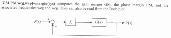
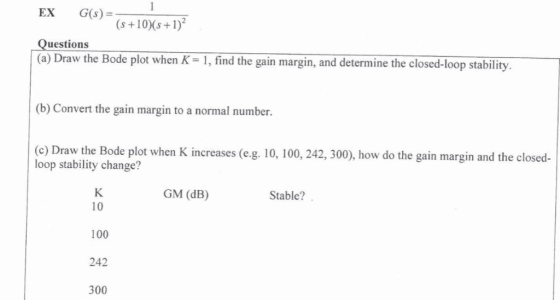

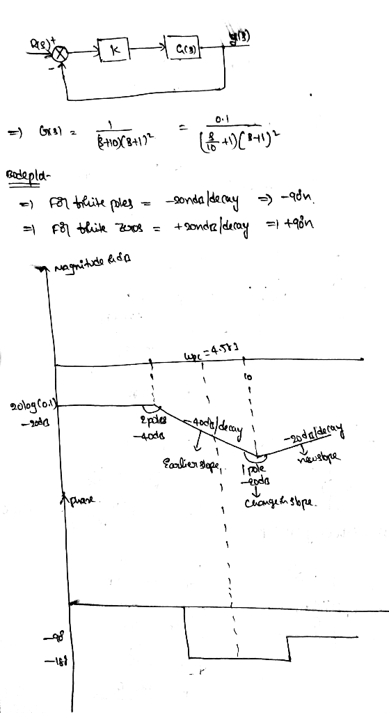
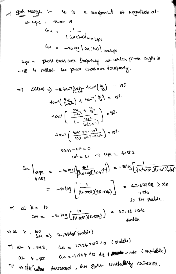
EX G(s)- (s +10(s+1)2 Questions Draw the Bode plot when K-1, find the gain margin, and determine the closed-loop stability. (b) Convert the gain margin to a normal number. (c) Draw the Bode plot when K increases (e.g. 10, 100, 242, 300), how do the gain margin and the closed- loop stability change? GM (dB) Stable? 10 100 242 300
(d) From the above discussion, what kind of conclusion can you make on the relation between the gain margin when K1 and the stable range of K?
Homework Answers
Add Answer to:
Please show all work and answer all the questions so I can learn how to do it on my own. Thank yo...
Figure 1 Problem 3 For the system shown in the above figure, where G(s) a) Draw...
 Figure 1 Problem 3 For the system shown in the above figure, where G(s) a) Draw a Bode diagram of the open-loop transfer function G(s) when K 10. b) On your plot, indicate the crossover frequencies, PM, and GM. Is the closed-loop system stable with K-10? c) Determine the value of K such that the phase margin is 30°. What are the gain margin and the crossover frequencies with this K? Note: You can finish problems 2-3 with the help...
I got A,B,C done can you do D,E,F Also can you check my solutions please. Thank...
 I got A,B,C done can you do D,E,F
Also can you check my solutions please. Thank you ?
Question 1 - Consider an unit feedback system whose open-loop transfer function is G(s)-k/ ((s + 1)(s 2 +4s 25)) A. Draw Bode plot of the open-loop system for k-75 B. Calculate the phase and magnitude of G(s) at 1 rad/s for k 75 C. Determine the cross-over frequency, and the phase and gain margins for k-75 (14 marks D. What is...
I got A,B,C done can you do D,E,F
Also can you check my solutions please. Thank you ?
Question 1 - Consider an unit feedback system whose open-loop transfer function is G(s)-k/ ((s + 1)(s 2 +4s 25)) A. Draw Bode plot of the open-loop system for k-75 B. Calculate the phase and magnitude of G(s) at 1 rad/s for k 75 C. Determine the cross-over frequency, and the phase and gain margins for k-75 (14 marks D. What is...
Please show all work and write neatly so I can understand how to do this on my own. Thank you. The transfer function of the given physical system is 2500 Gp(s)- P21000 The physical system is controll...
 Please show all work and write neatly so I can understand how to
do this on my own. Thank you.
The transfer function of the given physical system is 2500 Gp(s)- P21000 The physical system is controlled with a unity-feedback system shown below, E(s) R(s) + (a) Draw the bode plot of open-loop transfer function when K-1. (b) Use bode plot of open-loop transfer function to determine the type of system (do not use transfer function)
The transfer function of...
Please show all work and write neatly so I can understand how to
do this on my own. Thank you.
The transfer function of the given physical system is 2500 Gp(s)- P21000 The physical system is controlled with a unity-feedback system shown below, E(s) R(s) + (a) Draw the bode plot of open-loop transfer function when K-1. (b) Use bode plot of open-loop transfer function to determine the type of system (do not use transfer function)
The transfer function of...
You may prepare your answer in softcopy, print out and submit or use hardcopy approach. Put...
 You may prepare your answer in softcopy, print out and submit or use hardcopy approach. Put all your MATLAB codes and Simulink Diagram under the appendix. The system below is to be compensated to achieve a phase margin of 50 degrees. s +3 x(t) 5+2s+ 2s E-KH. yệt) Design gain and phase-lead compensator to achieve the desired PM of 45 degrees. +PART A: Uncompensated system analysis % created by Fakhera 2020 Determine the uncompensated PM and GM s=tf('s'); g= (5+3)/...
Answer all parts and show all work. Design a Pl or PDcontroller for the system Go)+...
 Answer all parts and show all work.
Design a Pl or PDcontroller for the system Go)+ 10 to meet the following specifications Zero steady state error for unit step reference input ·4 < 0.12s . %OS < 10%. (a) Determine the low frequency gain, crossover frequency and phase margin necessary to meet the (b) Decide if C() needs an integrator. Plot the Bode plot of either G(s) or G(o)/s, depending on (c) Use sisotool (or iteration) to choose a gain...
Answer all parts and show all work.
Design a Pl or PDcontroller for the system Go)+ 10 to meet the following specifications Zero steady state error for unit step reference input ·4 < 0.12s . %OS < 10%. (a) Determine the low frequency gain, crossover frequency and phase margin necessary to meet the (b) Decide if C() needs an integrator. Plot the Bode plot of either G(s) or G(o)/s, depending on (c) Use sisotool (or iteration) to choose a gain...
A2. (a) Explain how the open-loop polar plot can be used to assess closed-loop stability by...
 A2. (a) Explain how the open-loop polar plot can be used to assess closed-loop stability by applying Nyquist's stability criterion. Apply Nyquist's stability criterion to determine the stability condition for a closed-loop system that is unstable in the open-loop. [30%] = K (b) An unstable system has transfer function given by G(S) in which the gain K is S(S-2) positive. A derivative compensator H(s) = 0.5s + 1 is inserted in the negative feedback path to form a control loop....
5. Consider the feedback system in Figure 4 where! G(s) = 26+10% Figure 4 The Bode...
 5. Consider the feedback system in Figure 4 where! G(s) = 26+10% Figure 4 The Bode plot of G is shown in Figure 5. Boda Diagram Magnitude (dB) -100- -156 -135 -root -225 10 Frequency radici Figure 5: Bode plot of G (a) [2 marks] Find the phase margin, gain margin and gain crossover frequency (approximate as needed) for the case when C(s) = 1. PM = GM = wc = You are asked to design a feedback controller C(s)...
tions 11 and 12: Performance specifications of the system shown in Figure 4 are satisfied ifclo poles are located ats42j Design a lead compensator (find K and a) of the form Kso that the specifi...
 tions 11 and 12: Performance specifications of the system shown in Figure 4 are satisfied ifclo poles are located ats42j Design a lead compensator (find K and a) of the form Kso that the specification is met. s+20 Which of the following values of z meet the specification? - 3.33 C. :-2.86 D. 2-423 E. None of the above 2) Which of the following values of K meet the specification? A. K- 39.0 B. K-140 C. K-78.O D. K-280 E....
Spring 2019 3. Given a closed-loop control system with unity feedback is shown in the block...
 Spring 2019 3. Given a closed-loop control system with unity feedback is shown in the block diagram. G(s) is the open-loop transfer function, and the controller is a gain, K. 1. (20) Calculate the open-loop transfer function tar →Q--t G(s) (10) Calculate the steady-state error to a step input of the open-loop system. 7. (in Bode Form) from the Bode plot. (10) Calculate the shortest possible settling time with a percentage overshoot of 5% or less. 8. 2. (10)Plot the...
I need help with this so bad. Please answer ASAP. Thanks 1. For the transfer function...
 I need help with this so bad. Please answer ASAP. Thanks
1. For the transfer function given below, generate frequency response using bode command in MATLAB, and tabulate frequency response data (Frequency, Magnitude, Log Magnitude or dB and Phase) 50 G(s) (s+1)(s+2)(s5) a) Determine gain and phase margins from the frequency response table b) Verifiy the results using Bode diagrams c) Design a gain only compensator that results in a phase margin of 45 degrees Frequency response data can be...
I need help with this so bad. Please answer ASAP. Thanks
1. For the transfer function given below, generate frequency response using bode command in MATLAB, and tabulate frequency response data (Frequency, Magnitude, Log Magnitude or dB and Phase) 50 G(s) (s+1)(s+2)(s5) a) Determine gain and phase margins from the frequency response table b) Verifiy the results using Bode diagrams c) Design a gain only compensator that results in a phase margin of 45 degrees Frequency response data can be...
 Figure 1 Problem 3 For the system shown in the above figure, where G(s) a) Draw a Bode diagram of the open-loop transfer function G(s) when K 10. b) On your plot, indicate the crossover frequencies, PM, and GM. Is the closed-loop system stable with K-10? c) Determine the value of K such that the phase margin is 30°. What are the gain margin and the crossover frequencies with this K? Note: You can finish problems 2-3 with the help...
 I got A,B,C done can you do D,E,F
Also can you check my solutions please. Thank you ?
Question 1 - Consider an unit feedback system whose open-loop transfer function is G(s)-k/ ((s + 1)(s 2 +4s 25)) A. Draw Bode plot of the open-loop system for k-75 B. Calculate the phase and magnitude of G(s) at 1 rad/s for k 75 C. Determine the cross-over frequency, and the phase and gain margins for k-75 (14 marks D. What is...
I got A,B,C done can you do D,E,F
Also can you check my solutions please. Thank you ?
Question 1 - Consider an unit feedback system whose open-loop transfer function is G(s)-k/ ((s + 1)(s 2 +4s 25)) A. Draw Bode plot of the open-loop system for k-75 B. Calculate the phase and magnitude of G(s) at 1 rad/s for k 75 C. Determine the cross-over frequency, and the phase and gain margins for k-75 (14 marks D. What is...
 Please show all work and write neatly so I can understand how to
do this on my own. Thank you.
The transfer function of the given physical system is 2500 Gp(s)- P21000 The physical system is controlled with a unity-feedback system shown below, E(s) R(s) + (a) Draw the bode plot of open-loop transfer function when K-1. (b) Use bode plot of open-loop transfer function to determine the type of system (do not use transfer function)
The transfer function of...
Please show all work and write neatly so I can understand how to
do this on my own. Thank you.
The transfer function of the given physical system is 2500 Gp(s)- P21000 The physical system is controlled with a unity-feedback system shown below, E(s) R(s) + (a) Draw the bode plot of open-loop transfer function when K-1. (b) Use bode plot of open-loop transfer function to determine the type of system (do not use transfer function)
The transfer function of...
 You may prepare your answer in softcopy, print out and submit or use hardcopy approach. Put all your MATLAB codes and Simulink Diagram under the appendix. The system below is to be compensated to achieve a phase margin of 50 degrees. s +3 x(t) 5+2s+ 2s E-KH. yệt) Design gain and phase-lead compensator to achieve the desired PM of 45 degrees. +PART A: Uncompensated system analysis % created by Fakhera 2020 Determine the uncompensated PM and GM s=tf('s'); g= (5+3)/...
 Answer all parts and show all work.
Design a Pl or PDcontroller for the system Go)+ 10 to meet the following specifications Zero steady state error for unit step reference input ·4 < 0.12s . %OS < 10%. (a) Determine the low frequency gain, crossover frequency and phase margin necessary to meet the (b) Decide if C() needs an integrator. Plot the Bode plot of either G(s) or G(o)/s, depending on (c) Use sisotool (or iteration) to choose a gain...
Answer all parts and show all work.
Design a Pl or PDcontroller for the system Go)+ 10 to meet the following specifications Zero steady state error for unit step reference input ·4 < 0.12s . %OS < 10%. (a) Determine the low frequency gain, crossover frequency and phase margin necessary to meet the (b) Decide if C() needs an integrator. Plot the Bode plot of either G(s) or G(o)/s, depending on (c) Use sisotool (or iteration) to choose a gain...
 A2. (a) Explain how the open-loop polar plot can be used to assess closed-loop stability by applying Nyquist's stability criterion. Apply Nyquist's stability criterion to determine the stability condition for a closed-loop system that is unstable in the open-loop. [30%] = K (b) An unstable system has transfer function given by G(S) in which the gain K is S(S-2) positive. A derivative compensator H(s) = 0.5s + 1 is inserted in the negative feedback path to form a control loop....
 5. Consider the feedback system in Figure 4 where! G(s) = 26+10% Figure 4 The Bode plot of G is shown in Figure 5. Boda Diagram Magnitude (dB) -100- -156 -135 -root -225 10 Frequency radici Figure 5: Bode plot of G (a) [2 marks] Find the phase margin, gain margin and gain crossover frequency (approximate as needed) for the case when C(s) = 1. PM = GM = wc = You are asked to design a feedback controller C(s)...
 tions 11 and 12: Performance specifications of the system shown in Figure 4 are satisfied ifclo poles are located ats42j Design a lead compensator (find K and a) of the form Kso that the specification is met. s+20 Which of the following values of z meet the specification? - 3.33 C. :-2.86 D. 2-423 E. None of the above 2) Which of the following values of K meet the specification? A. K- 39.0 B. K-140 C. K-78.O D. K-280 E....
 Spring 2019 3. Given a closed-loop control system with unity feedback is shown in the block diagram. G(s) is the open-loop transfer function, and the controller is a gain, K. 1. (20) Calculate the open-loop transfer function tar →Q--t G(s) (10) Calculate the steady-state error to a step input of the open-loop system. 7. (in Bode Form) from the Bode plot. (10) Calculate the shortest possible settling time with a percentage overshoot of 5% or less. 8. 2. (10)Plot the...
 I need help with this so bad. Please answer ASAP. Thanks
1. For the transfer function given below, generate frequency response using bode command in MATLAB, and tabulate frequency response data (Frequency, Magnitude, Log Magnitude or dB and Phase) 50 G(s) (s+1)(s+2)(s5) a) Determine gain and phase margins from the frequency response table b) Verifiy the results using Bode diagrams c) Design a gain only compensator that results in a phase margin of 45 degrees Frequency response data can be...
I need help with this so bad. Please answer ASAP. Thanks
1. For the transfer function given below, generate frequency response using bode command in MATLAB, and tabulate frequency response data (Frequency, Magnitude, Log Magnitude or dB and Phase) 50 G(s) (s+1)(s+2)(s5) a) Determine gain and phase margins from the frequency response table b) Verifiy the results using Bode diagrams c) Design a gain only compensator that results in a phase margin of 45 degrees Frequency response data can be...
Most questions answered within 3 hours.
-
Angel Corporation has $10,000,000 of
8.0% 25 year bonds dated May 1, 2018 with interest payable...
asked 23 minutes ago -
7.
________ involves individuals trading goods they already have or
providing services in exchange for something...
asked 27 minutes ago -
Share your research problem. What databases did you search as
you gathered evidence to support your...
asked 27 minutes ago -
what process occurs to form microspores and megaspores in flowering
plants?
asked 34 minutes ago -
C++
I need to use the function getData to put in all my data using
arrays....
asked 34 minutes ago -
A block is hung by a string from the inside roof of a van. When
the...
asked 41 minutes ago -
Do you think companies should not go for long term debt in their
capital structure to...
asked 49 minutes ago -
I create an address book where the user enters the name, phone
and email in the...
asked 55 minutes ago -
The production capacity for acrylonitrile
(C3H3N) in the United States exceeds 2
million pounds per year....
asked 1 hour ago -
explain and comment out your answer
43. How many address lines are required to address a...
asked 1 hour ago -
A sample of 45 observations is selected from a normal
population. The sample mean is 49,...
asked 1 hour ago -
A construction company is planning to bid on a building
contract. The bid costs the company...
asked 1 hour ago