
Homework Answers

Add Answer to:
Problem B-4-1 Find the transfer function X (s)/X/(s) of the mechanical system shown in Figure 4-50....
Consider the mechanical system shown in Figure. Displacements Xi and Xo are measured from their respective...
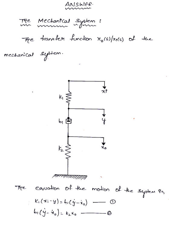
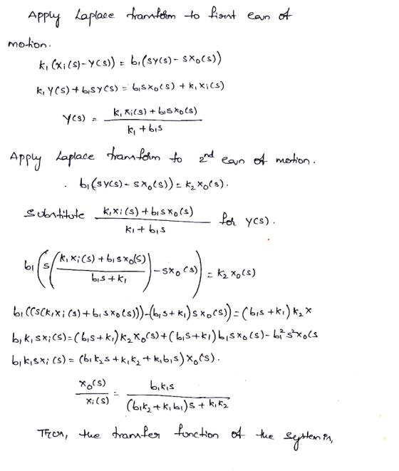
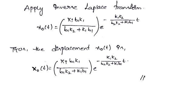
 Consider the mechanical system shown in Figure. Displacements Xi and Xo are measured from their respective equilibrium positions. Derive the transfer function of the system wherein Xi is the input and Xo is the output. Then obtain the response Xo (t) ki bi b,* when input Xi (t) is a step displacement of magnitude Xi occurring at t 0. Assume that Xo (0-) 0.
02 Obtain the transfer function Y(s)yU(s) of the system shown in Figure. The vertical motion u...
 02 Obtain the transfer function Y(s)yU(s) of the system shown in Figure. The vertical motion u at point P is the input. This system is a simplified version of an automobile or motorcycle suspension system. (In the figure mi and ki represent the wheel mass and tire stiffness, respectively.) Assume that the displacements x and y are measured from their respective equilibrium positions in the absence of the input u. Use Newton second law to derive the movement equations.
For the mechanical system shown below find the input-output equation relating xolt) to the displacement input...
 For the mechanical system shown below find the input-output equation relating xolt) to the displacement input x(t) 1. ド ド Ki Derive the transfer function X,G)/X, (s)of the mechanical system shown below. The displacements x, and xo are measured from their respective equilibrium potions. Is the system a first-order system if so, what is the time constant? 2. k1 bz k2 3. Consider the mechanical system shown below. The system is initially at rest. The displacements x, and x2 are...
Find transfer function given input force and input displacement
Consider the mechanical system shown in Figure 4-55. The system is at rest for t<0. The input force "u" is given at t=0. The displacement "x" is the output of thesystem and is measured from the equilibrium position. Obtain the transfer function X(s)/U(s) for "u" as a force AND for "u" as a displacement for the end of the node.
B-3-7. Obtain the XO (s)/ Xi (s) transfer function from each of the 3 mechanical systems in Figure 3-54. In the diagram...
 B-3-7. Obtain the XO (s)/ Xi (s) transfer function from each of the 3 mechanical systems in Figure 3-54. In the diagrams, xi represents the displacement and x0 denotes the departure displacement (each displacement is measured from from its equilibrium position INGENIERIA DE CONTROL MODERNA Figura 3-54 Sistemas mecánicos
B-3-7. Obtain the XO (s)/ Xi (s) transfer function from each of the 3 mechanical systems in Figure 3-54. In the diagrams, xi represents the displacement and x0 denotes the departure...
B-3-7. Obtain the XO (s)/ Xi (s) transfer function from each of the 3 mechanical systems in Figure 3-54. In the diagrams, xi represents the displacement and x0 denotes the departure displacement (each displacement is measured from from its equilibrium position INGENIERIA DE CONTROL MODERNA Figura 3-54 Sistemas mecánicos
B-3-7. Obtain the XO (s)/ Xi (s) transfer function from each of the 3 mechanical systems in Figure 3-54. In the diagrams, xi represents the displacement and x0 denotes the departure...
Question 3 (35 marks) Consider a mechanical system shown in Figure 3. The system is at rest for t
 Question 3 (35 marks) Consider a mechanical system shown in Figure 3. The system is at rest for t<0. The input force f is applied at 0. The displacement x is the output of the system and is measured from the equilibrium position. kI b2 bi it Figure 3. Schematic of a mechanical system. (a) Obtain the traf) (10 marks) X (s) F(s) (b) Use of force-voltage analogy, obtain the equations for an electrical system (5 marks) (c) Draw a...
7. Consider the mechanical system shown below. The system initially at rest. The displacements u, y,...
 7. Consider the mechanical system shown below. The system initially at rest. The displacements u, y, and z are measured from their respective rest positions. Given that u is the input, y is the output, 1) Obtain the transfer function of the system (20pt). 2) Obtain a state-space representation of the system (20pt). I b, - obteranlara k, 12 WI
For the system shown in Fig. 1, solve the following problems. (a) Find the transfer function, G(s...
 For the system shown in Fig. 1, solve the following problems. (a) Find the transfer function, G(s)X2 (s)/F(s) (b) Does the system oscillate with a unit step input (f (t))? Explain the reason (c) Decide if the system(x2 (t)) is stable with a unit step input (f (t))? Explain the reason 1. 320) 8 kg 2 N/m 4N-s/m 2N-s/m Fig. 1 2. There are two suspensions for a car as shown in Fig. 2 (a) Find the equations of each...
please show steps For the system shown in the figure. a. Find the transfer function 0,(s)/T(S)....
 please show steps
For the system shown in the figure. a. Find the transfer function 0,(s)/T(S). b. Find the damping Dyo yield a 20% gvershoot in output angular displacement for a step torque input. N =25 kg-r W3 10 N2=5 D N-m/rad N4 5 0000
For the system shown in the figure. a. Find the transfer function 0,(s)/T(S). b. Find the damping Dyo yield a 20% gvershoot in output angular displacement for a step torque input. N =25 kg-r W3...
please show steps
For the system shown in the figure. a. Find the transfer function 0,(s)/T(S). b. Find the damping Dyo yield a 20% gvershoot in output angular displacement for a step torque input. N =25 kg-r W3 10 N2=5 D N-m/rad N4 5 0000
For the system shown in the figure. a. Find the transfer function 0,(s)/T(S). b. Find the damping Dyo yield a 20% gvershoot in output angular displacement for a step torque input. N =25 kg-r W3...
Problem 2 Determine the transfer function 01(s)/M(s) for the shaft-gear mechanical system in the figure, where...
 Problem 2 Determine the transfer function 01(s)/M(s) for the shaft-gear mechanical system in the figure, where 1(s) and Ms) are the Laplace transforms of the angle 01(t) and of the moment m(t). Use the time-domain mathematical model of this system. Known are J1, ki, J2, c, k2, Ni and N2. N. 1000 0,m 0 000 N Problem 3 By using the transfer function 1(s)/Ms), determined in Problem 2, calculate and plot 01(t) using the step input command of MATLAB. Known...
 Consider the mechanical system shown in Figure. Displacements Xi and Xo are measured from their respective equilibrium positions. Derive the transfer function of the system wherein Xi is the input and Xo is the output. Then obtain the response Xo (t) ki bi b,* when input Xi (t) is a step displacement of magnitude Xi occurring at t 0. Assume that Xo (0-) 0.
 02 Obtain the transfer function Y(s)yU(s) of the system shown in Figure. The vertical motion u at point P is the input. This system is a simplified version of an automobile or motorcycle suspension system. (In the figure mi and ki represent the wheel mass and tire stiffness, respectively.) Assume that the displacements x and y are measured from their respective equilibrium positions in the absence of the input u. Use Newton second law to derive the movement equations.
 For the mechanical system shown below find the input-output equation relating xolt) to the displacement input x(t) 1. ド ド Ki Derive the transfer function X,G)/X, (s)of the mechanical system shown below. The displacements x, and xo are measured from their respective equilibrium potions. Is the system a first-order system if so, what is the time constant? 2. k1 bz k2 3. Consider the mechanical system shown below. The system is initially at rest. The displacements x, and x2 are...
 B-3-7. Obtain the XO (s)/ Xi (s) transfer function from each of the 3 mechanical systems in Figure 3-54. In the diagrams, xi represents the displacement and x0 denotes the departure displacement (each displacement is measured from from its equilibrium position INGENIERIA DE CONTROL MODERNA Figura 3-54 Sistemas mecánicos
B-3-7. Obtain the XO (s)/ Xi (s) transfer function from each of the 3 mechanical systems in Figure 3-54. In the diagrams, xi represents the displacement and x0 denotes the departure...
B-3-7. Obtain the XO (s)/ Xi (s) transfer function from each of the 3 mechanical systems in Figure 3-54. In the diagrams, xi represents the displacement and x0 denotes the departure displacement (each displacement is measured from from its equilibrium position INGENIERIA DE CONTROL MODERNA Figura 3-54 Sistemas mecánicos
B-3-7. Obtain the XO (s)/ Xi (s) transfer function from each of the 3 mechanical systems in Figure 3-54. In the diagrams, xi represents the displacement and x0 denotes the departure...
 Question 3 (35 marks) Consider a mechanical system shown in Figure 3. The system is at rest for t<0. The input force f is applied at 0. The displacement x is the output of the system and is measured from the equilibrium position. kI b2 bi it Figure 3. Schematic of a mechanical system. (a) Obtain the traf) (10 marks) X (s) F(s) (b) Use of force-voltage analogy, obtain the equations for an electrical system (5 marks) (c) Draw a...
 7. Consider the mechanical system shown below. The system initially at rest. The displacements u, y, and z are measured from their respective rest positions. Given that u is the input, y is the output, 1) Obtain the transfer function of the system (20pt). 2) Obtain a state-space representation of the system (20pt). I b, - obteranlara k, 12 WI
 For the system shown in Fig. 1, solve the following problems. (a) Find the transfer function, G(s)X2 (s)/F(s) (b) Does the system oscillate with a unit step input (f (t))? Explain the reason (c) Decide if the system(x2 (t)) is stable with a unit step input (f (t))? Explain the reason 1. 320) 8 kg 2 N/m 4N-s/m 2N-s/m Fig. 1 2. There are two suspensions for a car as shown in Fig. 2 (a) Find the equations of each...
 please show steps
For the system shown in the figure. a. Find the transfer function 0,(s)/T(S). b. Find the damping Dyo yield a 20% gvershoot in output angular displacement for a step torque input. N =25 kg-r W3 10 N2=5 D N-m/rad N4 5 0000
For the system shown in the figure. a. Find the transfer function 0,(s)/T(S). b. Find the damping Dyo yield a 20% gvershoot in output angular displacement for a step torque input. N =25 kg-r W3...
please show steps
For the system shown in the figure. a. Find the transfer function 0,(s)/T(S). b. Find the damping Dyo yield a 20% gvershoot in output angular displacement for a step torque input. N =25 kg-r W3 10 N2=5 D N-m/rad N4 5 0000
For the system shown in the figure. a. Find the transfer function 0,(s)/T(S). b. Find the damping Dyo yield a 20% gvershoot in output angular displacement for a step torque input. N =25 kg-r W3...
 Problem 2 Determine the transfer function 01(s)/M(s) for the shaft-gear mechanical system in the figure, where 1(s) and Ms) are the Laplace transforms of the angle 01(t) and of the moment m(t). Use the time-domain mathematical model of this system. Known are J1, ki, J2, c, k2, Ni and N2. N. 1000 0,m 0 000 N Problem 3 By using the transfer function 1(s)/Ms), determined in Problem 2, calculate and plot 01(t) using the step input command of MATLAB. Known...
Most questions answered within 3 hours.
-
While rotating the tires on your car you notice a rock [mass =
0.1 Kg] stuck...
asked 1 hour ago -
Using MARS simulator, write MIPS programs according to
the following scenarios: Receive a positive integer number...
asked 3 hours ago -
An object in front of a concave mirror has a real image that is
11.5 cm...
asked 3 hours ago -
Consider the reaction, C3 H8 + O2 --> CO2 + H2O. How many
moles of O2...
asked 5 hours ago -
You and your opponent both roll a fair die. If you both roll the
same number,...
asked 5 hours ago -
In a study of the accuracy of fast food drive-through orders,
Restaurant A had 257 accurate...
asked 5 hours ago -
Identify and describe in detail the four categories of
institutions that could be included in a...
asked 5 hours ago -
In python
class Customer:
def __init__(self, customer_id, last_name, first_name, phone_number, address):
self._customer_id = int(customer_id)
self._last_name =...
asked 5 hours ago -
What is an example of a limitation in implementing a new
ERP system and how it...
asked 5 hours ago -
In a section of 9.7cm of an artery with a radius of 2.6mm there
is a...
asked 5 hours ago -
the two carboxylic acid groups of aspartic acid have different
acidities with pKa values of 2.1...
asked 5 hours ago -
Would CuCO3 aqueous salt combined with calcium chloride
form a solid precipitate? If so, what would...
asked 5 hours ago
> Hey! I do think there is a small typo on the value that e is raised to, the denominator should be (b1k2+k1b1) I think. Please correct me if I am wrong or confirm if this is right. Thanks!
odris Mon, Jun 7, 2021 7:18 PM