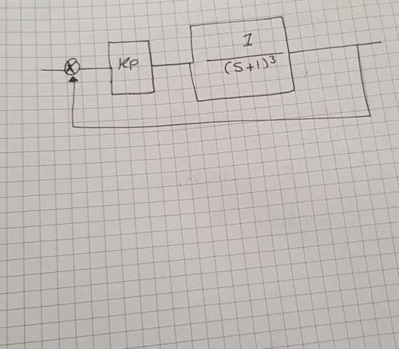
Control system:
Find the:
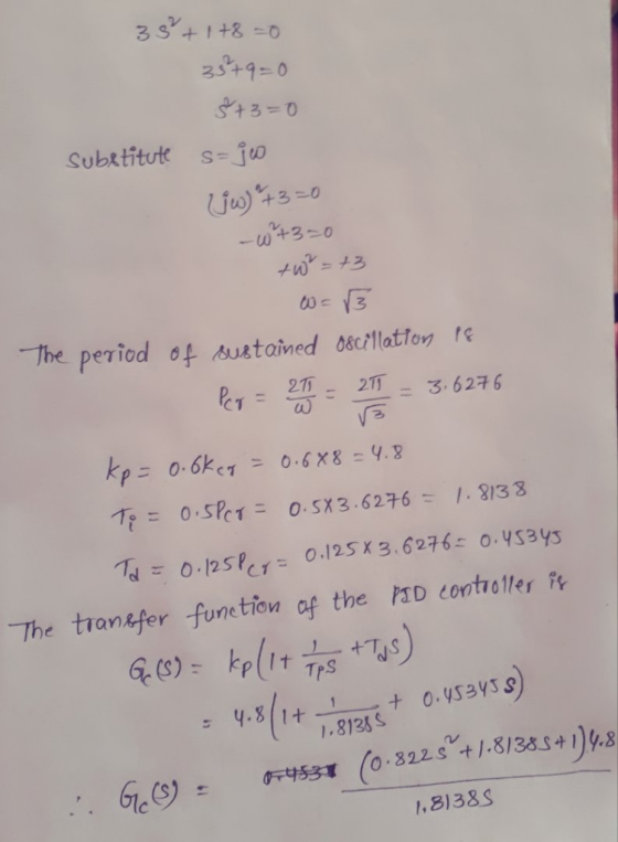
1- Characteristic equation.
2-PID controller has the transfer function (Kp,Ti ,Td,Kcr,Pcr).
Homework Answers

Add Answer to:
Control system: Find the: 1- Characteristic equation. 2-PID controller has the transfer function ...
Implement a PID controller to control the transfer function shown below. The PID controller and plant...
 Implement a PID controller to control the transfer function
shown below. The PID controller and plant transfer function should
be in a closed feedback loop. Assume the feedback loop has a Gain
of 5 associated with it i.e. . The Transfer function of a PID
controller is also given below. Start by:
6. Implement a PID controller to control the transfer function shown below. The PID feedback loop has a Gain of 5 associated with it i.e. (HS) = 5)....
Implement a PID controller to control the transfer function
shown below. The PID controller and plant transfer function should
be in a closed feedback loop. Assume the feedback loop has a Gain
of 5 associated with it i.e. . The Transfer function of a PID
controller is also given below. Start by:
6. Implement a PID controller to control the transfer function shown below. The PID feedback loop has a Gain of 5 associated with it i.e. (HS) = 5)....
Assume the following closed-loop system with a PID controller. Match the step responses with the appropriate...
 Assume the following closed-loop system with a PID controller. Match the step responses with the appropriate controller parameters. R(s) + PID Y(s) Controller G(s) 1. Step Response 1.5 data 0.5 0 10 40 50 20 30 Time (seconds) Kp = 2, Td = 1, Ti = 5 2. Step Response 1.5 =1, Kp = 5, Td Ti = 5 0.5 D 10 40 50 Кр = 10, Td = 1, T = 5 20 30 Time (seconds) Step Response 3....
7.16C). Given the control system shown in Figure P7.16 where the plant transfer function G(o) is given by 2.0 design a PID controller for this system. Cis) R(s) 2.0 sis+ 1)(s+3) Plant PID control...
 7.16C). Given the control system shown in Figure P7.16 where the plant transfer function G(o) is given by 2.0 design a PID controller for this system. Cis) R(s) 2.0 sis+ 1)(s+3) Plant PID controller FIGURE P7.16
7.16C). Given the control system shown in Figure P7.16 where the plant transfer function G(o) is given by 2.0 design a PID controller for this system. Cis) R(s) 2.0 sis+ 1)(s+3) Plant PID controller FIGURE P7.16
7.16C). Given the control system shown in Figure P7.16 where the plant transfer function G(o) is given by 2.0 design a PID controller for this system. Cis) R(s) 2.0 sis+ 1)(s+3) Plant PID controller FIGURE P7.16
Given the control system shown in Figure P7.I6 where the plant transfer function Gis) is given by лис, 2.0 Ds + 3) ss design a PID controller for this system. Cis) 2.0 sis + 1)(s+3 R(s) Plant PID...
 Given the control system shown in Figure P7.I6 where the plant transfer function Gis) is given by лис, 2.0 Ds + 3) ss design a PID controller for this system. Cis) 2.0 sis + 1)(s+3 R(s) Plant PID controller FIGURE P7.16
Given the control system shown in Figure P7.I6 where the plant transfer function Gis) is given by лис, 2.0 Ds + 3) ss design a PID controller for this system. Cis) 2.0 sis + 1)(s+3 R(s) Plant PID controller...
Given the control system shown in Figure P7.I6 where the plant transfer function Gis) is given by лис, 2.0 Ds + 3) ss design a PID controller for this system. Cis) 2.0 sis + 1)(s+3 R(s) Plant PID controller FIGURE P7.16
Given the control system shown in Figure P7.I6 where the plant transfer function Gis) is given by лис, 2.0 Ds + 3) ss design a PID controller for this system. Cis) 2.0 sis + 1)(s+3 R(s) Plant PID controller...
Tutorial -On PID control (Control System: Instructor slides and lab) Consider a second order mass...
 part 2 & part 3 please...
Tutorial -On PID control (Control System: Instructor slides and lab) Consider a second order mass-force system to study its behavior under various forms of PID control xtn fon force In Disturbance force: 50) (i.e. wind force) Part I (dealing with the plant/process) 1. What is the model of this system, in other words, write the ODE of the system 2. Derive the transfer function of the above system from Fls) to X(s) 3. What...
part 2 & part 3 please...
Tutorial -On PID control (Control System: Instructor slides and lab) Consider a second order mass-force system to study its behavior under various forms of PID control xtn fon force In Disturbance force: 50) (i.e. wind force) Part I (dealing with the plant/process) 1. What is the model of this system, in other words, write the ODE of the system 2. Derive the transfer function of the above system from Fls) to X(s) 3. What...
Consider the feedback sy PID COntroller Plant R(S) Y(s) the closed-loop transfer function T(s) = Y...
 Consider the feedback sy PID COntroller Plant R(S) Y(s) the closed-loop transfer function T(s) = Y controller (Kp Find er p 1, Ks K ) and show that the system is marginally stable with two imaginary roots. (s)/R(s) with no sabl thosed-loop transfer function T(s) Y (S/R(s) with the (three- term) PID controller added to stabilize the system. suming that Kd 4 and K, -100, find the values (range) of Kp that will stabilize the system.
I required to design a PID controller that has overshoot less than 10% with minimise rise...
 I required to design a PID controller that has overshoot less
than 10% with minimise rise time, settling time, peak time and
steady-state error.
The transfer function of the plant is shown below:
and the step response of the open loop system by using unit-step
is shown below:
Then I have designed my PID controller by referring to the
example from Modern Control Engineering 5th Edition by Katsuhiko
Ogata page 572 by using Ziegler Nichols 2nd Method.
I get Kcr...
I required to design a PID controller that has overshoot less
than 10% with minimise rise time, settling time, peak time and
steady-state error.
The transfer function of the plant is shown below:
and the step response of the open loop system by using unit-step
is shown below:
Then I have designed my PID controller by referring to the
example from Modern Control Engineering 5th Edition by Katsuhiko
Ogata page 572 by using Ziegler Nichols 2nd Method.
I get Kcr...
Question 6 The open-loop transfer function G(s) of a control system is given as G(8)- s(s+2)(s +5...
 Question 6 The open-loop transfer function G(s) of a control system is given as G(8)- s(s+2)(s +5) A proportional controller is used to control the system as shown in Figure 6 below: Y(s) R(s) + G(s) Figure 6: A control system with a proportional controller a) Assume Hp(s) is a proportional controller with the transfer function H,(s) kp. Determine, using the Routh-Hurwitz Stability Criterion, the value of kp for which the closed-loop system in Figure 6 is marginally stable. (6...
Do not fill the tables only,you must show all ste 2. Find the ZN parameters Output Response Set point are constant to 3 Ker increaseKer decrease Criticali Por-10se period K -3.5 not enough)-4 much)-3...
 Do not fill the tables only,you must show all ste 2. Find the ZN parameters Output Response Set point are constant to 3 Ker increaseKer decrease Criticali Por-10se period K -3.5 not enough)-4 much)-3. (too t (sec) 10 sec 20 sec From the graph find out Pscand Kcr Critical time Psr Critical gain, Kcr- Kcr P- Controller 0 PI- Controller 2.2 1.2 CI PID- Controller 7 8 Ti Td Kp P controller Pl controller PID controller
Do not fill the...
Do not fill the tables only,you must show all ste 2. Find the ZN parameters Output Response Set point are constant to 3 Ker increaseKer decrease Criticali Por-10se period K -3.5 not enough)-4 much)-3. (too t (sec) 10 sec 20 sec From the graph find out Pscand Kcr Critical time Psr Critical gain, Kcr- Kcr P- Controller 0 PI- Controller 2.2 1.2 CI PID- Controller 7 8 Ti Td Kp P controller Pl controller PID controller
Do not fill the...
PD & PID controller design Consider a unity feedback system with open loop transfer function, G(s)...
 PD & PID controller design Consider a unity feedback system with open loop transfer function, G(s) = 20/s(s+2)(8+4). Design a PD controller so that the closed loop has a damping ratio of 0.8 and natural frequency of oscillation as 2 rad/sec. b) 100 Consider a unity feedback system with open loop transfer function, aus. Design a PID controller, so that the phase margin of (S-1) (s + 2) (s+10) the system is 45° at a frequency of 4 rad/scc and...
 Implement a PID controller to control the transfer function
shown below. The PID controller and plant transfer function should
be in a closed feedback loop. Assume the feedback loop has a Gain
of 5 associated with it i.e. . The Transfer function of a PID
controller is also given below. Start by:
6. Implement a PID controller to control the transfer function shown below. The PID feedback loop has a Gain of 5 associated with it i.e. (HS) = 5)....
Implement a PID controller to control the transfer function
shown below. The PID controller and plant transfer function should
be in a closed feedback loop. Assume the feedback loop has a Gain
of 5 associated with it i.e. . The Transfer function of a PID
controller is also given below. Start by:
6. Implement a PID controller to control the transfer function shown below. The PID feedback loop has a Gain of 5 associated with it i.e. (HS) = 5)....
 Assume the following closed-loop system with a PID controller. Match the step responses with the appropriate controller parameters. R(s) + PID Y(s) Controller G(s) 1. Step Response 1.5 data 0.5 0 10 40 50 20 30 Time (seconds) Kp = 2, Td = 1, Ti = 5 2. Step Response 1.5 =1, Kp = 5, Td Ti = 5 0.5 D 10 40 50 Кр = 10, Td = 1, T = 5 20 30 Time (seconds) Step Response 3....
 7.16C). Given the control system shown in Figure P7.16 where the plant transfer function G(o) is given by 2.0 design a PID controller for this system. Cis) R(s) 2.0 sis+ 1)(s+3) Plant PID controller FIGURE P7.16
7.16C). Given the control system shown in Figure P7.16 where the plant transfer function G(o) is given by 2.0 design a PID controller for this system. Cis) R(s) 2.0 sis+ 1)(s+3) Plant PID controller FIGURE P7.16
7.16C). Given the control system shown in Figure P7.16 where the plant transfer function G(o) is given by 2.0 design a PID controller for this system. Cis) R(s) 2.0 sis+ 1)(s+3) Plant PID controller FIGURE P7.16
 Given the control system shown in Figure P7.I6 where the plant transfer function Gis) is given by лис, 2.0 Ds + 3) ss design a PID controller for this system. Cis) 2.0 sis + 1)(s+3 R(s) Plant PID controller FIGURE P7.16
Given the control system shown in Figure P7.I6 where the plant transfer function Gis) is given by лис, 2.0 Ds + 3) ss design a PID controller for this system. Cis) 2.0 sis + 1)(s+3 R(s) Plant PID controller...
Given the control system shown in Figure P7.I6 where the plant transfer function Gis) is given by лис, 2.0 Ds + 3) ss design a PID controller for this system. Cis) 2.0 sis + 1)(s+3 R(s) Plant PID controller FIGURE P7.16
Given the control system shown in Figure P7.I6 where the plant transfer function Gis) is given by лис, 2.0 Ds + 3) ss design a PID controller for this system. Cis) 2.0 sis + 1)(s+3 R(s) Plant PID controller...
 part 2 & part 3 please...
Tutorial -On PID control (Control System: Instructor slides and lab) Consider a second order mass-force system to study its behavior under various forms of PID control xtn fon force In Disturbance force: 50) (i.e. wind force) Part I (dealing with the plant/process) 1. What is the model of this system, in other words, write the ODE of the system 2. Derive the transfer function of the above system from Fls) to X(s) 3. What...
part 2 & part 3 please...
Tutorial -On PID control (Control System: Instructor slides and lab) Consider a second order mass-force system to study its behavior under various forms of PID control xtn fon force In Disturbance force: 50) (i.e. wind force) Part I (dealing with the plant/process) 1. What is the model of this system, in other words, write the ODE of the system 2. Derive the transfer function of the above system from Fls) to X(s) 3. What...
 Consider the feedback sy PID COntroller Plant R(S) Y(s) the closed-loop transfer function T(s) = Y controller (Kp Find er p 1, Ks K ) and show that the system is marginally stable with two imaginary roots. (s)/R(s) with no sabl thosed-loop transfer function T(s) Y (S/R(s) with the (three- term) PID controller added to stabilize the system. suming that Kd 4 and K, -100, find the values (range) of Kp that will stabilize the system.
 I required to design a PID controller that has overshoot less
than 10% with minimise rise time, settling time, peak time and
steady-state error.
The transfer function of the plant is shown below:
and the step response of the open loop system by using unit-step
is shown below:
Then I have designed my PID controller by referring to the
example from Modern Control Engineering 5th Edition by Katsuhiko
Ogata page 572 by using Ziegler Nichols 2nd Method.
I get Kcr...
I required to design a PID controller that has overshoot less
than 10% with minimise rise time, settling time, peak time and
steady-state error.
The transfer function of the plant is shown below:
and the step response of the open loop system by using unit-step
is shown below:
Then I have designed my PID controller by referring to the
example from Modern Control Engineering 5th Edition by Katsuhiko
Ogata page 572 by using Ziegler Nichols 2nd Method.
I get Kcr...
 Question 6 The open-loop transfer function G(s) of a control system is given as G(8)- s(s+2)(s +5) A proportional controller is used to control the system as shown in Figure 6 below: Y(s) R(s) + G(s) Figure 6: A control system with a proportional controller a) Assume Hp(s) is a proportional controller with the transfer function H,(s) kp. Determine, using the Routh-Hurwitz Stability Criterion, the value of kp for which the closed-loop system in Figure 6 is marginally stable. (6...
 Do not fill the tables only,you must show all ste 2. Find the ZN parameters Output Response Set point are constant to 3 Ker increaseKer decrease Criticali Por-10se period K -3.5 not enough)-4 much)-3. (too t (sec) 10 sec 20 sec From the graph find out Pscand Kcr Critical time Psr Critical gain, Kcr- Kcr P- Controller 0 PI- Controller 2.2 1.2 CI PID- Controller 7 8 Ti Td Kp P controller Pl controller PID controller
Do not fill the...
Do not fill the tables only,you must show all ste 2. Find the ZN parameters Output Response Set point are constant to 3 Ker increaseKer decrease Criticali Por-10se period K -3.5 not enough)-4 much)-3. (too t (sec) 10 sec 20 sec From the graph find out Pscand Kcr Critical time Psr Critical gain, Kcr- Kcr P- Controller 0 PI- Controller 2.2 1.2 CI PID- Controller 7 8 Ti Td Kp P controller Pl controller PID controller
Do not fill the...
 PD & PID controller design Consider a unity feedback system with open loop transfer function, G(s) = 20/s(s+2)(8+4). Design a PD controller so that the closed loop has a damping ratio of 0.8 and natural frequency of oscillation as 2 rad/sec. b) 100 Consider a unity feedback system with open loop transfer function, aus. Design a PID controller, so that the phase margin of (S-1) (s + 2) (s+10) the system is 45° at a frequency of 4 rad/scc and...
Most questions answered within 3 hours.
-
A block is hung by a string from the inside roof of a van. When
the...
asked 1 minute ago -
Do you think companies should not go for long term debt in their
capital structure to...
asked 10 minutes ago -
I create an address book where the user enters the name, phone
and email in the...
asked 16 minutes ago -
The production capacity for acrylonitrile
(C3H3N) in the United States exceeds 2
million pounds per year....
asked 24 minutes ago -
explain and comment out your answer
43. How many address lines are required to address a...
asked 30 minutes ago -
A sample of 45 observations is selected from a normal
population. The sample mean is 49,...
asked 45 minutes ago -
A construction company is planning to bid on a building
contract. The bid costs the company...
asked 42 minutes ago -
A firm operating in a purely competitive environment is faced
with a market price of $250....
asked 49 minutes ago -
•Let’s say someone claims the average population size is
600 feet squared and the housing authority...
asked 56 minutes ago -
Cynaide is a deadly poison that blocks the last step in the
electron transport chain of...
asked 1 hour ago -
Your friend tells you that there is a vending machine on campus
that dispenses M&M packs...
asked 1 hour ago -
What advantages are there to using piperidine rather than
hydroxide as a base?
asked 1 hour ago