
Homework Answers

Add Answer to:
6 Determine the power factor at location at which the generator must operate in the radial transmission system shown be...
Four-bus power system shown in Fig. 1 are as follows: Generator G1: 200 MVA, 7.2 kv,...
 Four-bus power system shown in Fig. 1 are as follows: Generator G1: 200 MVA, 7.2 kv, X -0.15 p.u Generator G2: 250 MVA, 9.6 kV, X-0.12 p.u Generator G3: 500 MVA, 10 kV, X-0.25 p.u Transformer T1:200 MVA, 7.2 Δ /132 Y kV, X= 0.05 p.u Transformer T2: 250 MVA, 9.6 Δ /132 Y kV, X =0.15 p.u Transformer T3: 500 MVA, 10 Δ /132 Y kV, x-0.1 p.u Each 132-kV line:X,-10 Ω 1- A three-phase short circuit occurs at...
Consider a 2-generator power system feeding a load through transmission network as shown in Figure below....
 Consider a 2-generator power system feeding a load through
transmission network as shown in Figure below. The impedance data
of the network is given in pu values on 100 MVA base. Using NR
method find the bus voltages after two i terations. The scheduled
power and nominal bus pu bus voltages are indicated in Figure
below.
Consider a 2-generator power system feeding a load through transmission network as shown in Figure 2. The impedance data of the network is given...
Consider a 2-generator power system feeding a load through
transmission network as shown in Figure below. The impedance data
of the network is given in pu values on 100 MVA base. Using NR
method find the bus voltages after two i terations. The scheduled
power and nominal bus pu bus voltages are indicated in Figure
below.
Consider a 2-generator power system feeding a load through transmission network as shown in Figure 2. The impedance data of the network is given...
Figure 1 Single line diagram b2 b3 b1 b4 grid Τι 13 A power system single line diagram is shown...
 Figure 1 Single line diagram b2 b3 b1 b4 grid Τι 13 A power system single line diagram is shown in Figure 1. The single line diagram shows a synchronous generator G connected to a large 50 Hz grid via its unit transformer T and a network of three transmission lines. Relevant details of the grid, transformer, generator and overhead lines are provided in Tables I,II,II & IV respectively. A double line to ground fault occurs at bus 3 Questions....
4.4 Voltage regulating transformer. Consider the following circuit in which the generator real and reactive power...
 4.4 Voltage regulating transformer. Consider the following circuit in which the generator real and reactive power output is 100.0 MW and -50 MVAr respec- tively: the generator voltage is 1.02 pu; the transformer impedance is Zt = 0.01 + 0.15 pu on a base of 180 MVA; and the transformer off-nominal tap setting is t-1.05 pu. Calculate the voltage magnitude at the network terminals. til P+jQ ZE Network Figure 3: Problem 4.4 - Circuit calculation with transformer off-nominal taps. 4.5...
Question 4 The power system shown is supplying a balanced wye-grounded resistive load that consumes the...
 Question 4 The power system shown is supplying a balanced wye-grounded resistive load that consumes the MW at 1.1 kV. An SLG fault occurs at bus 3. Determine the fault current and the voltages at the fault point. Assume that the fault resistance is 6.6 2. The equipment parameters are shown in the figure. 3 4 2 (1 (1 + j5) 2 10 MW Tuto 20 MVA 22/1.1 kV X = X2 = Xo = 0.05 pu Generator 30 MVA...
The six-bus system shown in Figure 1 will be simulated using MATLAB. Transmission line data and b...
 The six-bus system shown in Figure 1 will be simulated using MATLAB. Transmission line data and bus data are given in Tables 1 and 2 respectively. The transmission line data are calculated on 100 MVA base and 230 (line-to-line) kV base for generator. Tasks: 1. Determine the network admittance matrix Y 2. Find the load flow solution using Gauss-Seidel/Newton Raphson method until first iteration by manual calculation. Use Maltab software to solve power flow problem using Gauss-Seidel method. Find the...
The three-phase power and line-line ratings of the electric power system shown in Figure 2 are...
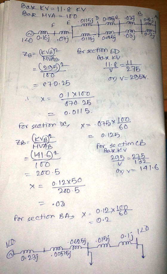
 The three-phase power and line-line ratings of the electric power system shown in Figure 2 are given below T2 2 Line Vm G M 1 BA Figure 2 One-line diagram for problem 2 G: Ti: T2: Line: M: 60 MVA 50 MVA 50 MVA 20 kV 20/200 kV 200/20 kV 200 kV 18 kV X=9% X=10% X=10% Z=120+j2002 X=8% 43.2 MVA (a) Draw an impedance diagram showing all impedances in per unit on a 100-MVA base. Choose 20 kV as...
2 - The three-phase power and line-line ratings of the electric power system shown in Figure...
 2 - The three-phase power and line-line ratings of the electric power system shown in Figure 2 are given below. Ti T2 VA Line 2 G M Vm BE BE Figure 2 One-line diagram for problem 2 G: T: T2: Line: M: 60 MVA 50 MVA 50 MVA 20 kV 20/200 kV 200/20 kV 200 kV 18 kV X=9% X=10% X=10% Z=120+j2002 X=8% 43.2 MVA (a) Draw an impedance diagram showing all impedances in per unit on a 100-MVA base....
The three-phase power and line-line ratings of the electric power system shown in Figure 2 are...
 The three-phase power and line-line ratings of the electric power system shown in Figure 2 are given below. T1 T2 V. 1 2 vm 9 Line G M Figure 2 One-line diagram for problem 2 G: T1: 60 MVA 50 MVA 50 MVA T2: Line: M: 20 kV 20/200 kV 200/20 kV 200 kV 18 kV X=9% X=10% X=10% Z=120+j200 12 X=8% 43.2 MVA (a) Draw an impedance diagram showing all impedances in per unit on a 100-MVA base. Choose...
3.1 When two four pole, 50 Hz synchronous generators are paralleled their phase displacement is 2...
 3.1 When two four pole, 50 Hz synchronous generators are paralleled their phase displacement is 2 mechanical. The synchronous reactance of each machine is 10 n/phase and the common busbar voltage is 66kV. Calculs the s cho nisimlengud AN 2 A synchronous generator has a synchronous impedance of 2p and a resist ance of 0.01 p.u. It is connected to an infinite busbar of voltage 1 pu. through a transformer of reactance 01 pou. If the generated (no-load) emfis 1.1...
 Four-bus power system shown in Fig. 1 are as follows: Generator G1: 200 MVA, 7.2 kv, X -0.15 p.u Generator G2: 250 MVA, 9.6 kV, X-0.12 p.u Generator G3: 500 MVA, 10 kV, X-0.25 p.u Transformer T1:200 MVA, 7.2 Δ /132 Y kV, X= 0.05 p.u Transformer T2: 250 MVA, 9.6 Δ /132 Y kV, X =0.15 p.u Transformer T3: 500 MVA, 10 Δ /132 Y kV, x-0.1 p.u Each 132-kV line:X,-10 Ω 1- A three-phase short circuit occurs at...
 Consider a 2-generator power system feeding a load through
transmission network as shown in Figure below. The impedance data
of the network is given in pu values on 100 MVA base. Using NR
method find the bus voltages after two i terations. The scheduled
power and nominal bus pu bus voltages are indicated in Figure
below.
Consider a 2-generator power system feeding a load through transmission network as shown in Figure 2. The impedance data of the network is given...
Consider a 2-generator power system feeding a load through
transmission network as shown in Figure below. The impedance data
of the network is given in pu values on 100 MVA base. Using NR
method find the bus voltages after two i terations. The scheduled
power and nominal bus pu bus voltages are indicated in Figure
below.
Consider a 2-generator power system feeding a load through transmission network as shown in Figure 2. The impedance data of the network is given...
 Figure 1 Single line diagram b2 b3 b1 b4 grid Τι 13 A power system single line diagram is shown in Figure 1. The single line diagram shows a synchronous generator G connected to a large 50 Hz grid via its unit transformer T and a network of three transmission lines. Relevant details of the grid, transformer, generator and overhead lines are provided in Tables I,II,II & IV respectively. A double line to ground fault occurs at bus 3 Questions....
 4.4 Voltage regulating transformer. Consider the following circuit in which the generator real and reactive power output is 100.0 MW and -50 MVAr respec- tively: the generator voltage is 1.02 pu; the transformer impedance is Zt = 0.01 + 0.15 pu on a base of 180 MVA; and the transformer off-nominal tap setting is t-1.05 pu. Calculate the voltage magnitude at the network terminals. til P+jQ ZE Network Figure 3: Problem 4.4 - Circuit calculation with transformer off-nominal taps. 4.5...
 Question 4 The power system shown is supplying a balanced wye-grounded resistive load that consumes the MW at 1.1 kV. An SLG fault occurs at bus 3. Determine the fault current and the voltages at the fault point. Assume that the fault resistance is 6.6 2. The equipment parameters are shown in the figure. 3 4 2 (1 (1 + j5) 2 10 MW Tuto 20 MVA 22/1.1 kV X = X2 = Xo = 0.05 pu Generator 30 MVA...
 The six-bus system shown in Figure 1 will be simulated using MATLAB. Transmission line data and bus data are given in Tables 1 and 2 respectively. The transmission line data are calculated on 100 MVA base and 230 (line-to-line) kV base for generator. Tasks: 1. Determine the network admittance matrix Y 2. Find the load flow solution using Gauss-Seidel/Newton Raphson method until first iteration by manual calculation. Use Maltab software to solve power flow problem using Gauss-Seidel method. Find the...
 The three-phase power and line-line ratings of the electric power system shown in Figure 2 are given below T2 2 Line Vm G M 1 BA Figure 2 One-line diagram for problem 2 G: Ti: T2: Line: M: 60 MVA 50 MVA 50 MVA 20 kV 20/200 kV 200/20 kV 200 kV 18 kV X=9% X=10% X=10% Z=120+j2002 X=8% 43.2 MVA (a) Draw an impedance diagram showing all impedances in per unit on a 100-MVA base. Choose 20 kV as...
 2 - The three-phase power and line-line ratings of the electric power system shown in Figure 2 are given below. Ti T2 VA Line 2 G M Vm BE BE Figure 2 One-line diagram for problem 2 G: T: T2: Line: M: 60 MVA 50 MVA 50 MVA 20 kV 20/200 kV 200/20 kV 200 kV 18 kV X=9% X=10% X=10% Z=120+j2002 X=8% 43.2 MVA (a) Draw an impedance diagram showing all impedances in per unit on a 100-MVA base....
 The three-phase power and line-line ratings of the electric power system shown in Figure 2 are given below. T1 T2 V. 1 2 vm 9 Line G M Figure 2 One-line diagram for problem 2 G: T1: 60 MVA 50 MVA 50 MVA T2: Line: M: 20 kV 20/200 kV 200/20 kV 200 kV 18 kV X=9% X=10% X=10% Z=120+j200 12 X=8% 43.2 MVA (a) Draw an impedance diagram showing all impedances in per unit on a 100-MVA base. Choose...
 3.1 When two four pole, 50 Hz synchronous generators are paralleled their phase displacement is 2 mechanical. The synchronous reactance of each machine is 10 n/phase and the common busbar voltage is 66kV. Calculs the s cho nisimlengud AN 2 A synchronous generator has a synchronous impedance of 2p and a resist ance of 0.01 p.u. It is connected to an infinite busbar of voltage 1 pu. through a transformer of reactance 01 pou. If the generated (no-load) emfis 1.1...
Most questions answered within 3 hours.
-
Group Policies
Research GROUP POLICY OBJECTS (GPO'S)
You can start in the Windows Server 2012 eBook...
asked 2 minutes ago -
software engineering
Problems.
Create a use case diagram for class registration for a
university.
Create a...
asked 2 minutes ago -
You are trying to convince your friend who wants to attend
medical school to take BY123...
asked 17 minutes ago -
Subject: C++
I have created a class called QueueOfIntegers in a file called
QueueOfIntegers.h, which is...
asked 17 minutes ago -
calculate the number of molecules of gas in a
container of 2.0 liter at 30 degrees...
asked 34 minutes ago -
1.which of the following is a phototroph?
a. sulfolobus
b. chloroflexus
c. bacteroidetes
d. deinococcus radioduran...
asked 30 minutes ago -
The group of companies LC "High-precision measuring instruments"
is the global provider of measurement, analysis and...
asked 36 minutes ago -
I want to write a python function to find the minimum
I have an nested list:...
asked 36 minutes ago -
Convert the high level language programming statementts to 80x86
assembly, Assume X=AX and y=BX
for (i=1;...
asked 45 minutes ago -
SoleMate’s Burkins sneakers cost $40 per pair from the supplier
and are sold by SoleMate at...
asked 49 minutes ago -
The movie Moneyball (based on the book by Michael
Lewis) tells the story of Billy Beane,...
asked 48 minutes ago -
A regional highway uses 8 tollbooths that are open to all
vehicles. A chi-square goodness-of-fit test...
asked 52 minutes ago