
Homework Answers
![Solu Hon given that DI POD MOON → FAB 2450 FBD at Joint FAE -Dx =0 Dx=0] to &ty=0 Ay - 2000 Ay+ by = youn Ay = 400-200 (@=0](http://img.homeworklib.com/questions/767cafc0-2b9b-11eb-abcd-9b35e731d17c.png?x-oss-process=image/resize,w_560)
Add Answer to:
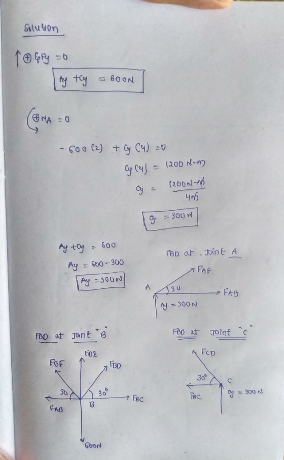
3. Determine the reactions at the supports and then draw a FBD at joint A, B,...
Determine the reactions at the bearing supports A, B, and C of the shaft, then draw...
 Determine the reactions at the bearing supports A, B, and C of
the shaft, then draw the shear and moment diagrams. EI is constant.
Each bearing exerts only vertical reactions on the shaft.
400 N 400 N
Determine the reactions at the bearing supports A, B, and C of
the shaft, then draw the shear and moment diagrams. EI is constant.
Each bearing exerts only vertical reactions on the shaft.
400 N 400 N
4. (a) Draw the free-body diagram of the beam. (b) Determine the reactions at the supports....
 4. (a) Draw the free-body diagram of the beam. (b) Determine the reactions at the supports. 100 lb 400 lb 900 ft-lb 4 ft 4 ft 3 ft
Q2 Determine the reactions at the supports A, B and C. Then draw the shear and...
 Q2 Determine the reactions at the supports A, B and C. Then draw the shear and moment diagrams. EI is constant. 80 kN 3 ,80 KN 3 12 kN/m 3 m n D E L 12 m EI = Constant
3. Determine the reactions at the supports shown in the following figure. The beam has a...
 3. Determine the reactions at the supports shown in the following figure. The beam has a roller joint at A and a pin joint at B. (25 points) 900 N/m 600 N/m
Please draw a fbd too. Q7. Determine the support reactions at B and C. 2 kN...
 Please draw a fbd too.
Q7. Determine the support reactions at B and C. 2 kN 5 kN A 3 kN 4 kN 6m 3m 3m 4m4m4m 4m
Please draw a fbd too.
Q7. Determine the support reactions at B and C. 2 kN 5 kN A 3 kN 4 kN 6m 3m 3m 4m4m4m 4m
a) Draw a single FBD and write the ONE Equilibrium equation that will allow you to determine By. Calculate By. b) Assuming you calculated By to be 500N, draw FBD that will allow you to calculate...
 a) Draw a single FBD and write the ONE Equilibrium equation
that will allow you to determine By. Calculate By.
b) Assuming you calculated By to be 500N, draw FBD that will
allow you to calculate Bx, with a single equation. Calculate
Bx
Problem 2: For the frame below, determine the reactions at B by completing parts a) and b) below 0.5 m 0.5 m 0.5 m 250 N
Problem 2: For the frame below, determine the reactions at B...
a) Draw a single FBD and write the ONE Equilibrium equation
that will allow you to determine By. Calculate By.
b) Assuming you calculated By to be 500N, draw FBD that will
allow you to calculate Bx, with a single equation. Calculate
Bx
Problem 2: For the frame below, determine the reactions at B by completing parts a) and b) below 0.5 m 0.5 m 0.5 m 250 N
Problem 2: For the frame below, determine the reactions at B...
1. Draw the FBD (s) of the beam system below and find the reactions at A. B and D. Please note that A B, and D are...
 1. Draw the FBD (s) of the beam system below and find the reactions at A. B and D. Please note that A B, and D are pins, C is rigid joint. (10) NOTE BE CAREFUL WITH THE UNITS ON THE DISTRIBUTED LOAD it is in kN/m and the point loads are in kN. (10) 10 kN 20 kN 2 m -2 m -- 2 m 10 k C 3 kN/m 4m D A -3 m
1. Draw the FBD...
1. Draw the FBD (s) of the beam system below and find the reactions at A. B and D. Please note that A B, and D are pins, C is rigid joint. (10) NOTE BE CAREFUL WITH THE UNITS ON THE DISTRIBUTED LOAD it is in kN/m and the point loads are in kN. (10) 10 kN 20 kN 2 m -2 m -- 2 m 10 k C 3 kN/m 4m D A -3 m
1. Draw the FBD...
Draw FBD of external forces at point A, B and E. Determine the support reaction at...
 Draw FBD of external forces at point A, B and E. Determine the
support reaction at A horizontally. Determine the support reaction
at A vertically. Determine the support reaction at B vertically.
Determine the support reaction at B horizontally. Draw FBD of
forces at point A. Determine the force in AC and state whether it
is in Tension (T) or Compression (C). Draw FBD of forces at point
E. Determine the force in EC and state whether it is in...
Draw FBD of external forces at point A, B and E. Determine the
support reaction at A horizontally. Determine the support reaction
at A vertically. Determine the support reaction at B vertically.
Determine the support reaction at B horizontally. Draw FBD of
forces at point A. Determine the force in AC and state whether it
is in Tension (T) or Compression (C). Draw FBD of forces at point
E. Determine the force in EC and state whether it is in...
Q3. a. Determine the reactions at supports A and B for the beam as shown in...
 Q3. a. Determine the reactions at supports A and B for the beam as shown in figure below. (Assume support A is a roller and support B hinged) 15.01 22 N/m 15 N 50 Nm B А 6.5 m 3.5 m b. Draw the free body diagram of each of the blocks given in the figure below. [2.5)
For the beam shown, draw the reactions at supports A and B in the positive direction,...
 For the beam shown, draw the reactions at supports A and B in
the positive direction, and also draw the shear and bending moment
in the positive direction on your FBD.
where w=23 kip/ft L=5 ft
find
w kip ft C A B L/3 ft L ft The shear equation across the beam. kip ENTER X 2 tries remaining. 1 point(s) possible The bending moment equation across the beam. kip.ft ENTER 3 tries remaining. 1 point(s) possible The internal shear...
For the beam shown, draw the reactions at supports A and B in
the positive direction, and also draw the shear and bending moment
in the positive direction on your FBD.
where w=23 kip/ft L=5 ft
find
w kip ft C A B L/3 ft L ft The shear equation across the beam. kip ENTER X 2 tries remaining. 1 point(s) possible The bending moment equation across the beam. kip.ft ENTER 3 tries remaining. 1 point(s) possible The internal shear...
 Determine the reactions at the bearing supports A, B, and C of
the shaft, then draw the shear and moment diagrams. EI is constant.
Each bearing exerts only vertical reactions on the shaft.
400 N 400 N
Determine the reactions at the bearing supports A, B, and C of
the shaft, then draw the shear and moment diagrams. EI is constant.
Each bearing exerts only vertical reactions on the shaft.
400 N 400 N
 4. (a) Draw the free-body diagram of the beam. (b) Determine the reactions at the supports. 100 lb 400 lb 900 ft-lb 4 ft 4 ft 3 ft
 Q2 Determine the reactions at the supports A, B and C. Then draw the shear and moment diagrams. EI is constant. 80 kN 3 ,80 KN 3 12 kN/m 3 m n D E L 12 m EI = Constant
 3. Determine the reactions at the supports shown in the following figure. The beam has a roller joint at A and a pin joint at B. (25 points) 900 N/m 600 N/m
 Please draw a fbd too.
Q7. Determine the support reactions at B and C. 2 kN 5 kN A 3 kN 4 kN 6m 3m 3m 4m4m4m 4m
Please draw a fbd too.
Q7. Determine the support reactions at B and C. 2 kN 5 kN A 3 kN 4 kN 6m 3m 3m 4m4m4m 4m
 a) Draw a single FBD and write the ONE Equilibrium equation
that will allow you to determine By. Calculate By.
b) Assuming you calculated By to be 500N, draw FBD that will
allow you to calculate Bx, with a single equation. Calculate
Bx
Problem 2: For the frame below, determine the reactions at B by completing parts a) and b) below 0.5 m 0.5 m 0.5 m 250 N
Problem 2: For the frame below, determine the reactions at B...
a) Draw a single FBD and write the ONE Equilibrium equation
that will allow you to determine By. Calculate By.
b) Assuming you calculated By to be 500N, draw FBD that will
allow you to calculate Bx, with a single equation. Calculate
Bx
Problem 2: For the frame below, determine the reactions at B by completing parts a) and b) below 0.5 m 0.5 m 0.5 m 250 N
Problem 2: For the frame below, determine the reactions at B...
 1. Draw the FBD (s) of the beam system below and find the reactions at A. B and D. Please note that A B, and D are pins, C is rigid joint. (10) NOTE BE CAREFUL WITH THE UNITS ON THE DISTRIBUTED LOAD it is in kN/m and the point loads are in kN. (10) 10 kN 20 kN 2 m -2 m -- 2 m 10 k C 3 kN/m 4m D A -3 m
1. Draw the FBD...
1. Draw the FBD (s) of the beam system below and find the reactions at A. B and D. Please note that A B, and D are pins, C is rigid joint. (10) NOTE BE CAREFUL WITH THE UNITS ON THE DISTRIBUTED LOAD it is in kN/m and the point loads are in kN. (10) 10 kN 20 kN 2 m -2 m -- 2 m 10 k C 3 kN/m 4m D A -3 m
1. Draw the FBD...
 Draw FBD of external forces at point A, B and E. Determine the
support reaction at A horizontally. Determine the support reaction
at A vertically. Determine the support reaction at B vertically.
Determine the support reaction at B horizontally. Draw FBD of
forces at point A. Determine the force in AC and state whether it
is in Tension (T) or Compression (C). Draw FBD of forces at point
E. Determine the force in EC and state whether it is in...
Draw FBD of external forces at point A, B and E. Determine the
support reaction at A horizontally. Determine the support reaction
at A vertically. Determine the support reaction at B vertically.
Determine the support reaction at B horizontally. Draw FBD of
forces at point A. Determine the force in AC and state whether it
is in Tension (T) or Compression (C). Draw FBD of forces at point
E. Determine the force in EC and state whether it is in...
 Q3. a. Determine the reactions at supports A and B for the beam as shown in figure below. (Assume support A is a roller and support B hinged) 15.01 22 N/m 15 N 50 Nm B А 6.5 m 3.5 m b. Draw the free body diagram of each of the blocks given in the figure below. [2.5)
 For the beam shown, draw the reactions at supports A and B in
the positive direction, and also draw the shear and bending moment
in the positive direction on your FBD.
where w=23 kip/ft L=5 ft
find
w kip ft C A B L/3 ft L ft The shear equation across the beam. kip ENTER X 2 tries remaining. 1 point(s) possible The bending moment equation across the beam. kip.ft ENTER 3 tries remaining. 1 point(s) possible The internal shear...
For the beam shown, draw the reactions at supports A and B in
the positive direction, and also draw the shear and bending moment
in the positive direction on your FBD.
where w=23 kip/ft L=5 ft
find
w kip ft C A B L/3 ft L ft The shear equation across the beam. kip ENTER X 2 tries remaining. 1 point(s) possible The bending moment equation across the beam. kip.ft ENTER 3 tries remaining. 1 point(s) possible The internal shear...
Most questions answered within 3 hours.
-
What is an example of a limitation in implementing a new
ERP system and how it...
asked 1 minute ago -
In a section of 9.7cm of an artery with a radius of 2.6mm there
is a...
asked 2 minutes ago -
the two carboxylic acid groups of aspartic acid have different
acidities with pKa values of 2.1...
asked 6 minutes ago -
Would CuCO3 aqueous salt combined with calcium chloride
form a solid precipitate? If so, what would...
asked 5 minutes ago -
In python
class Customer:
def __init__(self, customer_id, last_name, first_name, phone_number, address):
self._customer_id = int(customer_id)
self._last_name =...
asked 6 minutes ago -
How do ECM Solutions assist in embedding a culture of continuous
improvement in an organization? (Project...
asked 26 minutes ago -
Directions
These directions introduce the idea of Essential Questions.
Since this may be a new concept...
asked 28 minutes ago -
1.b. Fiscal policy is said to suffer from ‘crowding out’.
Explain what this means and why...
asked 45 minutes ago -
The equation for the reaction of nitrogen and oxygen to form
nitrogen oxide is written as...
asked 50 minutes ago -
A scientist reproducing some photoelectric effect experiments
shines a light on a metal electrode, but doesn't...
asked 52 minutes ago -
In a study designed to test the effectiveness of magnets for
treating back pain, 35 patients...
asked 1 hour ago -
Here are summary statistics for randomly selected weights of
newborn girls:
nequals=193,
x overbarxequals=30.5
hg,
sequals=7.3...
asked 1 hour ago