

Homework Answers
Greetings!!
Excitation table for T FF:

State table:

Minimaization:

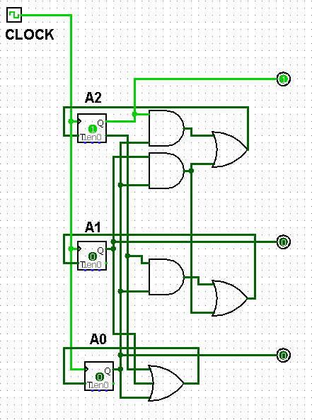
Implementation in logisim:
Hope this helps
Thank You
Add Answer to:
Need help understanding and doing this type of problem. Will upvote
for clear instructions, please! (parts...
Its logic design my sequence is 127605 i need help with all this pages please and thank you
 Its logic design
my sequence is 127605
i need help with all this pages please and thank you
27 60 Experiment 4 Six-State Up-Down Counter 1 Objective To become familiar with the design procedures of a counter, which are applicable to the design of other synchronous sequential circuits. 2 Problem description A six-state up-down counter is to be designed. Three flip-flops with outputs Q2,Qi and Qo are required in the design. As shown in Figure 1, the counter is initialized...
Its logic design
my sequence is 127605
i need help with all this pages please and thank you
27 60 Experiment 4 Six-State Up-Down Counter 1 Objective To become familiar with the design procedures of a counter, which are applicable to the design of other synchronous sequential circuits. 2 Problem description A six-state up-down counter is to be designed. Three flip-flops with outputs Q2,Qi and Qo are required in the design. As shown in Figure 1, the counter is initialized...
bilbecome famillar with t Objective design of other smchronos e pieos 2A Problem description six-state up-down...
 bilbecome famillar with t Objective design of other smchronos e pieos 2A Problem description six-state up-down co and Qo are required in the desidesi are rotvpulse to the REETInuo a posal state Se where the normal countet direcion Te the circuit in the initial st the RES hown in Fres flip-opw wi the RESET input is O during KESET Input of the couner th counting sequence is signal Cwa reversed irc- s an up-counter. The RES So 0. Ss S4...
14. Design a cyclic counter that produces the binary sequence 0, 2, 3,1. o..if the control signal...
 14?
14. Design a cyclic counter that produces the binary sequence 0, 2, 3,1. o..if the control signal X is 0 but produces the binary sequence 0, 1,3,2.0, if the control signal X is1.Use D flip-flops. (a) Draw the state diagram; (6 points (b) Draw the input, present state-next state, excitation table: (6 points) (c) Derive the minimal SOP expressions for the D inputs of the flip-flops using K-maps. Draw the logic circuit realization of the counter, using only NAND...
14?
14. Design a cyclic counter that produces the binary sequence 0, 2, 3,1. o..if the control signal X is 0 but produces the binary sequence 0, 1,3,2.0, if the control signal X is1.Use D flip-flops. (a) Draw the state diagram; (6 points (b) Draw the input, present state-next state, excitation table: (6 points) (c) Derive the minimal SOP expressions for the D inputs of the flip-flops using K-maps. Draw the logic circuit realization of the counter, using only NAND...
Design a three-bit counter using D flip-flops that has the following characteristics: When the value of...
 Design a three-bit counter using D flip-flops that has the following characteristics: When the value of an input x is 0, the counter counts "down" in standard order. When the value of x is 1, the counter counts "up" in standard order a. First, complete the state table shown below Present State Next State Excitation 0 0 0 0 0 0 1 0 0 0 0 0 0 b. Next, derive the logic equations using the Karnaugh maps shown below...
6. Design a 2-bit binary counter that counts, 0, 1, 2, 3, 0,. Use the 74LS374 IC, which has eight D flip-flops on it. They are positive-edge triggered, but it will not matter at all here You may draw...
 6. Design a 2-bit binary counter that counts, 0, 1, 2, 3, 0,. Use the 74LS374 IC, which has eight D flip-flops on it. They are positive-edge triggered, but it will not matter at all here You may draw a state diagram and then fill in the table Present State Q(t) Next State (D(t) - Q(t+1)) Q1(t) Qo(t) 7. Design a BCD binary counter that counts from 0 to 9 then back to 0 and repeat, displaying the count on...
hi i need answers for nos. 18-28. 1. In a counter, a flip-flop output 10. A...
 hi i need answers for nos. 18-28.
1. In a counter, a flip-flop output 10. A is a group of flip-flops, each one of which transition serves as a source for triggering other flip-flops, not by the common clock pulses. shares a common clock and is capable of storing one bit of information. A) RAM B) latch A ripple Cring (rather than signal transitions) are referred to as B synchronous D binary C) counter D) register 11. The Characteristic Equation...
hi i need answers for nos. 18-28.
1. In a counter, a flip-flop output 10. A is a group of flip-flops, each one of which transition serves as a source for triggering other flip-flops, not by the common clock pulses. shares a common clock and is capable of storing one bit of information. A) RAM B) latch A ripple Cring (rather than signal transitions) are referred to as B synchronous D binary C) counter D) register 11. The Characteristic Equation...
Digital Logic Design Need help with homework. Also need to create Logisim circuit with results. T...
 Digital Logic Design
Need help with homework.
Also need to create Logisim circuit with results.
Thank you!
Your IDs gn project, spring semester Your name 19 Digital Logic Design. Mid-semester desi This is a synchronous counter design. Tables and Karnaugh maps are provided. Do this alone, do not consult with friends except for general structions guidance-I want to see your design. Design, Synchronous counter. (#2 of 3) (repeat). That is QdQcQbQa-0001 (one), 0010 (t Note: Qa is the I.s.b. Design...
Digital Logic Design
Need help with homework.
Also need to create Logisim circuit with results.
Thank you!
Your IDs gn project, spring semester Your name 19 Digital Logic Design. Mid-semester desi This is a synchronous counter design. Tables and Karnaugh maps are provided. Do this alone, do not consult with friends except for general structions guidance-I want to see your design. Design, Synchronous counter. (#2 of 3) (repeat). That is QdQcQbQa-0001 (one), 0010 (t Note: Qa is the I.s.b. Design...
Design a synchronous counter that counts up 0, 1, 2, 3, 0, 1, 2, 3, ......
Design a synchronous counter that counts up 0, 1, 2, 3, 0, 1, 2, 3, ... when an input x = 1, and down when x = 0 using (a) D flip-flops. (b) J-K flip-flops. You need to show the state definition table, the state transition diagram, the state transition table, the K-maps for the respective logic functions and the schematic of the implementation using flipflops and logic gates in (a) as well as the K-maps for the logic functions...
Design an up/down counter with four states (0, 1, 2, 3) using clocked J-K flip-flops. A...
 Design an up/down counter with four states (0, 1, 2, 3) using clocked J-K flip-flops. A control signal x is used as follows: When x 0 the machine counts forward (up), when x , backward (down). Simulate using MultiSim and attach a simulation printout X Please address the following in your report 1. State Table 2. State Diagram 3. Flip-Flop Excitation Tables 4 K-Map Simplification and resulting diagram 5. Multisim Simulation 6. Conclusion/Discussion 7. References
Design an up/down counter with...
Design an up/down counter with four states (0, 1, 2, 3) using clocked J-K flip-flops. A control signal x is used as follows: When x 0 the machine counts forward (up), when x , backward (down). Simulate using MultiSim and attach a simulation printout X Please address the following in your report 1. State Table 2. State Diagram 3. Flip-Flop Excitation Tables 4 K-Map Simplification and resulting diagram 5. Multisim Simulation 6. Conclusion/Discussion 7. References
Design an up/down counter with...
Please work on Part E & F Given the State Table Below Q1 Q2 Q3 X-1 X-0 X-1 10111loloi A. Draw a state Diagram (5 points) B. Create the "design truth table" for the "next state" an...
 Please work on Part E & F
Given the State Table Below Q1 Q2 Q3 X-1 X-0 X-1 10111loloi A. Draw a state Diagram (5 points) B. Create the "design truth table" for the "next state" and the "output"' (5 points) C. Make a Karnaugh for each "next state" and the "output" (10 points) When making the Karnaugh maps, "xQ1" should be along the top and "0203" along the side (The two missing states should be considered "DONT CARES") Write...
Please work on Part E & F
Given the State Table Below Q1 Q2 Q3 X-1 X-0 X-1 10111loloi A. Draw a state Diagram (5 points) B. Create the "design truth table" for the "next state" and the "output"' (5 points) C. Make a Karnaugh for each "next state" and the "output" (10 points) When making the Karnaugh maps, "xQ1" should be along the top and "0203" along the side (The two missing states should be considered "DONT CARES") Write...
 Its logic design
my sequence is 127605
i need help with all this pages please and thank you
27 60 Experiment 4 Six-State Up-Down Counter 1 Objective To become familiar with the design procedures of a counter, which are applicable to the design of other synchronous sequential circuits. 2 Problem description A six-state up-down counter is to be designed. Three flip-flops with outputs Q2,Qi and Qo are required in the design. As shown in Figure 1, the counter is initialized...
Its logic design
my sequence is 127605
i need help with all this pages please and thank you
27 60 Experiment 4 Six-State Up-Down Counter 1 Objective To become familiar with the design procedures of a counter, which are applicable to the design of other synchronous sequential circuits. 2 Problem description A six-state up-down counter is to be designed. Three flip-flops with outputs Q2,Qi and Qo are required in the design. As shown in Figure 1, the counter is initialized...
 bilbecome famillar with t Objective design of other smchronos e pieos 2A Problem description six-state up-down co and Qo are required in the desidesi are rotvpulse to the REETInuo a posal state Se where the normal countet direcion Te the circuit in the initial st the RES hown in Fres flip-opw wi the RESET input is O during KESET Input of the couner th counting sequence is signal Cwa reversed irc- s an up-counter. The RES So 0. Ss S4...
 14?
14. Design a cyclic counter that produces the binary sequence 0, 2, 3,1. o..if the control signal X is 0 but produces the binary sequence 0, 1,3,2.0, if the control signal X is1.Use D flip-flops. (a) Draw the state diagram; (6 points (b) Draw the input, present state-next state, excitation table: (6 points) (c) Derive the minimal SOP expressions for the D inputs of the flip-flops using K-maps. Draw the logic circuit realization of the counter, using only NAND...
14?
14. Design a cyclic counter that produces the binary sequence 0, 2, 3,1. o..if the control signal X is 0 but produces the binary sequence 0, 1,3,2.0, if the control signal X is1.Use D flip-flops. (a) Draw the state diagram; (6 points (b) Draw the input, present state-next state, excitation table: (6 points) (c) Derive the minimal SOP expressions for the D inputs of the flip-flops using K-maps. Draw the logic circuit realization of the counter, using only NAND...
 Design a three-bit counter using D flip-flops that has the following characteristics: When the value of an input x is 0, the counter counts "down" in standard order. When the value of x is 1, the counter counts "up" in standard order a. First, complete the state table shown below Present State Next State Excitation 0 0 0 0 0 0 1 0 0 0 0 0 0 b. Next, derive the logic equations using the Karnaugh maps shown below...
 6. Design a 2-bit binary counter that counts, 0, 1, 2, 3, 0,. Use the 74LS374 IC, which has eight D flip-flops on it. They are positive-edge triggered, but it will not matter at all here You may draw a state diagram and then fill in the table Present State Q(t) Next State (D(t) - Q(t+1)) Q1(t) Qo(t) 7. Design a BCD binary counter that counts from 0 to 9 then back to 0 and repeat, displaying the count on...
 hi i need answers for nos. 18-28.
1. In a counter, a flip-flop output 10. A is a group of flip-flops, each one of which transition serves as a source for triggering other flip-flops, not by the common clock pulses. shares a common clock and is capable of storing one bit of information. A) RAM B) latch A ripple Cring (rather than signal transitions) are referred to as B synchronous D binary C) counter D) register 11. The Characteristic Equation...
hi i need answers for nos. 18-28.
1. In a counter, a flip-flop output 10. A is a group of flip-flops, each one of which transition serves as a source for triggering other flip-flops, not by the common clock pulses. shares a common clock and is capable of storing one bit of information. A) RAM B) latch A ripple Cring (rather than signal transitions) are referred to as B synchronous D binary C) counter D) register 11. The Characteristic Equation...
 Digital Logic Design
Need help with homework.
Also need to create Logisim circuit with results.
Thank you!
Your IDs gn project, spring semester Your name 19 Digital Logic Design. Mid-semester desi This is a synchronous counter design. Tables and Karnaugh maps are provided. Do this alone, do not consult with friends except for general structions guidance-I want to see your design. Design, Synchronous counter. (#2 of 3) (repeat). That is QdQcQbQa-0001 (one), 0010 (t Note: Qa is the I.s.b. Design...
Digital Logic Design
Need help with homework.
Also need to create Logisim circuit with results.
Thank you!
Your IDs gn project, spring semester Your name 19 Digital Logic Design. Mid-semester desi This is a synchronous counter design. Tables and Karnaugh maps are provided. Do this alone, do not consult with friends except for general structions guidance-I want to see your design. Design, Synchronous counter. (#2 of 3) (repeat). That is QdQcQbQa-0001 (one), 0010 (t Note: Qa is the I.s.b. Design...
 Design an up/down counter with four states (0, 1, 2, 3) using clocked J-K flip-flops. A control signal x is used as follows: When x 0 the machine counts forward (up), when x , backward (down). Simulate using MultiSim and attach a simulation printout X Please address the following in your report 1. State Table 2. State Diagram 3. Flip-Flop Excitation Tables 4 K-Map Simplification and resulting diagram 5. Multisim Simulation 6. Conclusion/Discussion 7. References
Design an up/down counter with...
Design an up/down counter with four states (0, 1, 2, 3) using clocked J-K flip-flops. A control signal x is used as follows: When x 0 the machine counts forward (up), when x , backward (down). Simulate using MultiSim and attach a simulation printout X Please address the following in your report 1. State Table 2. State Diagram 3. Flip-Flop Excitation Tables 4 K-Map Simplification and resulting diagram 5. Multisim Simulation 6. Conclusion/Discussion 7. References
Design an up/down counter with...
 Please work on Part E & F
Given the State Table Below Q1 Q2 Q3 X-1 X-0 X-1 10111loloi A. Draw a state Diagram (5 points) B. Create the "design truth table" for the "next state" and the "output"' (5 points) C. Make a Karnaugh for each "next state" and the "output" (10 points) When making the Karnaugh maps, "xQ1" should be along the top and "0203" along the side (The two missing states should be considered "DONT CARES") Write...
Please work on Part E & F
Given the State Table Below Q1 Q2 Q3 X-1 X-0 X-1 10111loloi A. Draw a state Diagram (5 points) B. Create the "design truth table" for the "next state" and the "output"' (5 points) C. Make a Karnaugh for each "next state" and the "output" (10 points) When making the Karnaugh maps, "xQ1" should be along the top and "0203" along the side (The two missing states should be considered "DONT CARES") Write...
Most questions answered within 3 hours.
-
Suppose that you know that in the population of full-time
employees in the United States, the...
asked 1 minute ago -
This experiment was designed originally to sample various meat and carcass quality
aspects of Ontario pigs...
asked 2 minutes ago -
) Raw materials are studied for contamination. Suppose that
the number of particles of contamination per...
asked 16 minutes ago -
After running a regression analysis we calculated an F test and
the significance level was 0.15....
asked 12 minutes ago -
----Can someone please help me solve this one using JAVA
----I thank you in advance
Create...
asked 16 minutes ago -
1. What force primarily attracts the potassium ion to
the nitrate ion?
a. London forces...
asked 18 minutes ago -
What are the negative effects of abruptly stopping the use of
all fossil fuels? Give at...
asked 25 minutes ago -
Given that many conflict are the result of different parties having
different interests, is it possible...
asked 30 minutes ago -
A 750 g block can slide uniformly along the horizontal track
when a string attached to...
asked 33 minutes ago -
In 2017, Juan entered into a contract to write a book. The
publisher advanced Juan $50,000,...
asked 46 minutes ago -
Determine the number of kinds of protons in each molecule (w/
respect to NMR spectroscopy). Drawing...
asked 56 minutes ago -
A jeweler whose near point is 68 cm from his eye uses a
magnifying glass as...
asked 55 minutes ago