
We have designed a 2NAND and 3NAND.
Homework Answers
Add Answer to:
We have designed a 2NAND and 3NAND.
1. Use the cells you have already constructed to...
a) (5 marks) Explain the difference between a latch, a gated latch and a flip flop....
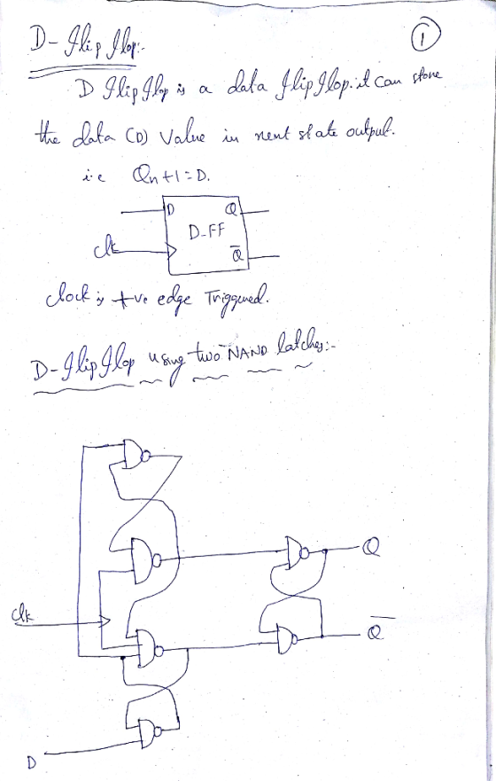
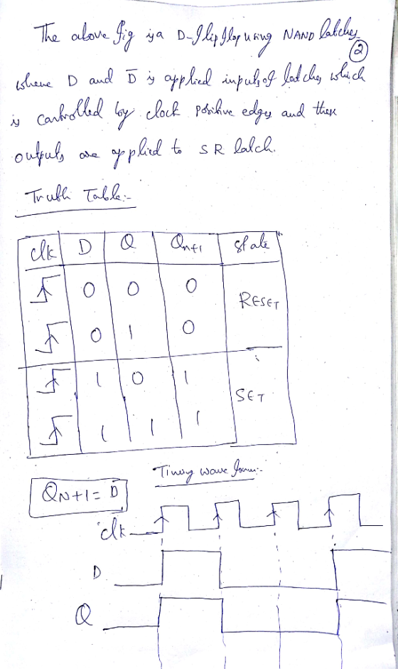
 a) (5 marks) Explain the difference between a latch, a gated latch and a flip flop. b) (5 marks) A gated SR latch has the following schematic diagram CLK a) Draw a timing diagram showing the Q and Q outputs for the following sequence of inputs: CLK R Assume that the initial state of the outputs is Q 0 and Q 1 c) (5 marks) Draw a schematic diagram for a rising edge-triggered master-slave D flip- flop built using two...
Use the Quartus Prime Text Editor to implement a behavioral model of the D flip-flop described ab...
 Use the Quartus Prime Text Editor to implement a behavioral
model of the D flip-flop described above in a file named
d_flops.sv. Specify the D flip-flop’s module according to the
interface specification given in the table below.
Port
Mode
Data Type
Size
Description
RST
in
logic
1-bit
Active high asynchronous reset
CLK
in
logic
1-bit
Synchronizing clock signal
EN
in
logic
1-bit
Synchronous clock enable
D
in
logic
1-bit
Synchronous data input
Q
out
logic
1-bit
Current/present state
Qbar
out...
Use the Quartus Prime Text Editor to implement a behavioral
model of the D flip-flop described above in a file named
d_flops.sv. Specify the D flip-flop’s module according to the
interface specification given in the table below.
Port
Mode
Data Type
Size
Description
RST
in
logic
1-bit
Active high asynchronous reset
CLK
in
logic
1-bit
Synchronizing clock signal
EN
in
logic
1-bit
Synchronous clock enable
D
in
logic
1-bit
Synchronous data input
Q
out
logic
1-bit
Current/present state
Qbar
out...
QUESTION 7 A master slave flip flop behaves similarly to a clocked latch, except that the...
 QUESTION 7 A master slave flip flop behaves similarly to a clocked latch, except that the latches output can change only near the rising edge of the clock True False QUESTION 8 Assuming zero setup and hold times, clocked latches and flip-flops produce the same outputs as long as the inputs do not change while the clock is asserted True False QUESTIONS An edge-triggered D flip-flop requires more internal gates than a similar device constructed from a J-K master-slave flip...
3. Answer the following questions about a data flip-flop (D-Flip Flop): a) (4 ps) Write the VHDL required to define a rising-edge triggered (RET) D-Flip Flop with additional clock enable (CEN) an...
 3. Answer the following questions about a data flip-flop (D-Flip Flop): a) (4 ps) Write the VHDL required to define a rising-edge triggered (RET) D-Flip Flop with additional clock enable (CEN) and reset inputs. Your reset may be synchronous or asynchronous. Assume any input, output, or signal variables that you require have already been declared in VHDL (you do not have to write the declarations for these) b) [I pal ls your reset syachronous or asynchronous for the D-Flip Flop...
1. Complete the waveform of Qoutput based on the given set of inputs. C is the...
 1. Complete the waveform of Qoutput based on the given set of inputs. C is the clock input. (2 marks) C. I к e 2. Complete the waveform of Qoutput from a D flip-flop based on the given set of inputs. C is the clock input. Notice this flip-flop has two asynchronous inputs. Notice the overhead bars above some signal names. (2 marks) c 30 Ro D e 3. Both J and Kinputs of a JK flip-flop are tied to...
P.s last part with explanation be written explicitly if possible. Thx from now on The question...
 P.s last part with explanation be written explicitly if
possible. Thx from now on
The question is mainly consisted from two sub-parts, respectively. A) (30 pts) According to the RS flip flop schematic given below, with using the outputs and clock signal, draw the probable Set (S) and Reset (R) input signals. с R s R o 10 B) (70 pts) An extremely popular version of an S-R flip flop can be called as J-K flip flop. The 2 parts...
P.s last part with explanation be written explicitly if
possible. Thx from now on
The question is mainly consisted from two sub-parts, respectively. A) (30 pts) According to the RS flip flop schematic given below, with using the outputs and clock signal, draw the probable Set (S) and Reset (R) input signals. с R s R o 10 B) (70 pts) An extremely popular version of an S-R flip flop can be called as J-K flip flop. The 2 parts...
how slove 4-34, 4-35, 4-36??? I dont know that! please hlep me! 306 □ CHAPTER 4/SEQUENTIAL CIRCUITS OTABLE 4-16...
 how slove 4-34, 4-35, 4-36??? I dont know that! please hlep me!
306 □ CHAPTER 4/SEQUENTIAL CIRCUITS OTABLE 4-16 State Table for Problem 4-33 Next State Input Output Present State 4-36 4-37 0 0 0 0 4-38 Design the circuit specified by Table 4-14 and use the sequence from Problen 4-31 (either yours or the one posted on the text website) to perform an automatic logic simulation-based verification of your design. 4 433. The state table for a sequential circuit...
how slove 4-34, 4-35, 4-36??? I dont know that! please hlep me!
306 □ CHAPTER 4/SEQUENTIAL CIRCUITS OTABLE 4-16 State Table for Problem 4-33 Next State Input Output Present State 4-36 4-37 0 0 0 0 4-38 Design the circuit specified by Table 4-14 and use the sequence from Problen 4-31 (either yours or the one posted on the text website) to perform an automatic logic simulation-based verification of your design. 4 433. The state table for a sequential circuit...
Use the Quartus Prime Text Editor to implement a structural model of the 4-bit data register show...
 Use the Quartus Prime Text Editor to implement a structural
model of the 4-bit data register shown above in a file named
reg_4bit.sv. Specify the 4-bit data register’s module according to
the interface specification given in the table below.
Port
Mode
Data Type
Size
Description
RST
in
logic
1-bit
Active high asynchronous reset
CLK
in
logic
1-bit
Synchronizing clock signal
EN
in
logic
1-bit
Synchronous clock enable
D
in
logic vector
4-bits
Synchronous data input
Q
out
logic vector
4-bits...
Use the Quartus Prime Text Editor to implement a structural
model of the 4-bit data register shown above in a file named
reg_4bit.sv. Specify the 4-bit data register’s module according to
the interface specification given in the table below.
Port
Mode
Data Type
Size
Description
RST
in
logic
1-bit
Active high asynchronous reset
CLK
in
logic
1-bit
Synchronizing clock signal
EN
in
logic
1-bit
Synchronous clock enable
D
in
logic vector
4-bits
Synchronous data input
Q
out
logic vector
4-bits...
please give the verilog code and explain in the form of comments. Part I Consider the...
 please give the verilog code and explain in the form
of comments.
Part I Consider the circuit in Figure 1. It is a 4-bit synchronous counter (text Section 5.9.2) that uses four T-type flip- flops (text Section 5.5). The counter increments its value on each positive edge of the clock if the Enable signal is asserted. The counter is reset to 0 by setting the Clear b signal low - it is an active-low asynchronous clear. You are to implement...
please give the verilog code and explain in the form
of comments.
Part I Consider the circuit in Figure 1. It is a 4-bit synchronous counter (text Section 5.9.2) that uses four T-type flip- flops (text Section 5.5). The counter increments its value on each positive edge of the clock if the Enable signal is asserted. The counter is reset to 0 by setting the Clear b signal low - it is an active-low asynchronous clear. You are to implement...
hi i need answers for nos. 18-28. 1. In a counter, a flip-flop output 10. A...
 hi i need answers for nos. 18-28.
1. In a counter, a flip-flop output 10. A is a group of flip-flops, each one of which transition serves as a source for triggering other flip-flops, not by the common clock pulses. shares a common clock and is capable of storing one bit of information. A) RAM B) latch A ripple Cring (rather than signal transitions) are referred to as B synchronous D binary C) counter D) register 11. The Characteristic Equation...
hi i need answers for nos. 18-28.
1. In a counter, a flip-flop output 10. A is a group of flip-flops, each one of which transition serves as a source for triggering other flip-flops, not by the common clock pulses. shares a common clock and is capable of storing one bit of information. A) RAM B) latch A ripple Cring (rather than signal transitions) are referred to as B synchronous D binary C) counter D) register 11. The Characteristic Equation...
 a) (5 marks) Explain the difference between a latch, a gated latch and a flip flop. b) (5 marks) A gated SR latch has the following schematic diagram CLK a) Draw a timing diagram showing the Q and Q outputs for the following sequence of inputs: CLK R Assume that the initial state of the outputs is Q 0 and Q 1 c) (5 marks) Draw a schematic diagram for a rising edge-triggered master-slave D flip- flop built using two...
 Use the Quartus Prime Text Editor to implement a behavioral
model of the D flip-flop described above in a file named
d_flops.sv. Specify the D flip-flop’s module according to the
interface specification given in the table below.
Port
Mode
Data Type
Size
Description
RST
in
logic
1-bit
Active high asynchronous reset
CLK
in
logic
1-bit
Synchronizing clock signal
EN
in
logic
1-bit
Synchronous clock enable
D
in
logic
1-bit
Synchronous data input
Q
out
logic
1-bit
Current/present state
Qbar
out...
Use the Quartus Prime Text Editor to implement a behavioral
model of the D flip-flop described above in a file named
d_flops.sv. Specify the D flip-flop’s module according to the
interface specification given in the table below.
Port
Mode
Data Type
Size
Description
RST
in
logic
1-bit
Active high asynchronous reset
CLK
in
logic
1-bit
Synchronizing clock signal
EN
in
logic
1-bit
Synchronous clock enable
D
in
logic
1-bit
Synchronous data input
Q
out
logic
1-bit
Current/present state
Qbar
out...
 QUESTION 7 A master slave flip flop behaves similarly to a clocked latch, except that the latches output can change only near the rising edge of the clock True False QUESTION 8 Assuming zero setup and hold times, clocked latches and flip-flops produce the same outputs as long as the inputs do not change while the clock is asserted True False QUESTIONS An edge-triggered D flip-flop requires more internal gates than a similar device constructed from a J-K master-slave flip...
 3. Answer the following questions about a data flip-flop (D-Flip Flop): a) (4 ps) Write the VHDL required to define a rising-edge triggered (RET) D-Flip Flop with additional clock enable (CEN) and reset inputs. Your reset may be synchronous or asynchronous. Assume any input, output, or signal variables that you require have already been declared in VHDL (you do not have to write the declarations for these) b) [I pal ls your reset syachronous or asynchronous for the D-Flip Flop...
 1. Complete the waveform of Qoutput based on the given set of inputs. C is the clock input. (2 marks) C. I к e 2. Complete the waveform of Qoutput from a D flip-flop based on the given set of inputs. C is the clock input. Notice this flip-flop has two asynchronous inputs. Notice the overhead bars above some signal names. (2 marks) c 30 Ro D e 3. Both J and Kinputs of a JK flip-flop are tied to...
 P.s last part with explanation be written explicitly if
possible. Thx from now on
The question is mainly consisted from two sub-parts, respectively. A) (30 pts) According to the RS flip flop schematic given below, with using the outputs and clock signal, draw the probable Set (S) and Reset (R) input signals. с R s R o 10 B) (70 pts) An extremely popular version of an S-R flip flop can be called as J-K flip flop. The 2 parts...
P.s last part with explanation be written explicitly if
possible. Thx from now on
The question is mainly consisted from two sub-parts, respectively. A) (30 pts) According to the RS flip flop schematic given below, with using the outputs and clock signal, draw the probable Set (S) and Reset (R) input signals. с R s R o 10 B) (70 pts) An extremely popular version of an S-R flip flop can be called as J-K flip flop. The 2 parts...
 how slove 4-34, 4-35, 4-36??? I dont know that! please hlep me!
306 □ CHAPTER 4/SEQUENTIAL CIRCUITS OTABLE 4-16 State Table for Problem 4-33 Next State Input Output Present State 4-36 4-37 0 0 0 0 4-38 Design the circuit specified by Table 4-14 and use the sequence from Problen 4-31 (either yours or the one posted on the text website) to perform an automatic logic simulation-based verification of your design. 4 433. The state table for a sequential circuit...
how slove 4-34, 4-35, 4-36??? I dont know that! please hlep me!
306 □ CHAPTER 4/SEQUENTIAL CIRCUITS OTABLE 4-16 State Table for Problem 4-33 Next State Input Output Present State 4-36 4-37 0 0 0 0 4-38 Design the circuit specified by Table 4-14 and use the sequence from Problen 4-31 (either yours or the one posted on the text website) to perform an automatic logic simulation-based verification of your design. 4 433. The state table for a sequential circuit...
 Use the Quartus Prime Text Editor to implement a structural
model of the 4-bit data register shown above in a file named
reg_4bit.sv. Specify the 4-bit data register’s module according to
the interface specification given in the table below.
Port
Mode
Data Type
Size
Description
RST
in
logic
1-bit
Active high asynchronous reset
CLK
in
logic
1-bit
Synchronizing clock signal
EN
in
logic
1-bit
Synchronous clock enable
D
in
logic vector
4-bits
Synchronous data input
Q
out
logic vector
4-bits...
Use the Quartus Prime Text Editor to implement a structural
model of the 4-bit data register shown above in a file named
reg_4bit.sv. Specify the 4-bit data register’s module according to
the interface specification given in the table below.
Port
Mode
Data Type
Size
Description
RST
in
logic
1-bit
Active high asynchronous reset
CLK
in
logic
1-bit
Synchronizing clock signal
EN
in
logic
1-bit
Synchronous clock enable
D
in
logic vector
4-bits
Synchronous data input
Q
out
logic vector
4-bits...
 please give the verilog code and explain in the form
of comments.
Part I Consider the circuit in Figure 1. It is a 4-bit synchronous counter (text Section 5.9.2) that uses four T-type flip- flops (text Section 5.5). The counter increments its value on each positive edge of the clock if the Enable signal is asserted. The counter is reset to 0 by setting the Clear b signal low - it is an active-low asynchronous clear. You are to implement...
please give the verilog code and explain in the form
of comments.
Part I Consider the circuit in Figure 1. It is a 4-bit synchronous counter (text Section 5.9.2) that uses four T-type flip- flops (text Section 5.5). The counter increments its value on each positive edge of the clock if the Enable signal is asserted. The counter is reset to 0 by setting the Clear b signal low - it is an active-low asynchronous clear. You are to implement...
 hi i need answers for nos. 18-28.
1. In a counter, a flip-flop output 10. A is a group of flip-flops, each one of which transition serves as a source for triggering other flip-flops, not by the common clock pulses. shares a common clock and is capable of storing one bit of information. A) RAM B) latch A ripple Cring (rather than signal transitions) are referred to as B synchronous D binary C) counter D) register 11. The Characteristic Equation...
hi i need answers for nos. 18-28.
1. In a counter, a flip-flop output 10. A is a group of flip-flops, each one of which transition serves as a source for triggering other flip-flops, not by the common clock pulses. shares a common clock and is capable of storing one bit of information. A) RAM B) latch A ripple Cring (rather than signal transitions) are referred to as B synchronous D binary C) counter D) register 11. The Characteristic Equation...
Most questions answered within 3 hours.
-
(Expected rate of return and risk) Carter Inc. is evaluating a
security. Calculate the investment’s expected...
asked 1 hour ago -
What specific indicators can point to lack of progress for
African Americans in American society?
asked 2 hours ago -
1-The Electrons in a beam are moving at 2.7×10⁸ m/s in an
electric field of 15000...
asked 3 hours ago -
A gas tank is a vertical cylinder. It has a radius of 1m, a
height of...
asked 3 hours ago -
Accent Software faces the following conditions. All of these
support Accent’s use of a market-penetration pricing...
asked 4 hours ago -
A mathematically inclined friend emails you the following
instructions: "Meet me in the cafeteria the first...
asked 4 hours ago -
A monopoly sells in two countries . The demand curves in the two
countries are p1...
asked 5 hours ago -
A .15kg rubber ball is bounced off a wall. Before hitting the
wall, the ball moves...
asked 6 hours ago -
A manufacturing company preparing to build a new plant is
considering three potential locations for it....
asked 6 hours ago -
B. If compound Y has approximately the same values of solubility
in toluene as compound X,...
asked 6 hours ago -
Oscar Inc. has inventory in Japan valued at 39,051,000 Yen one
year ago. One year ago...
asked 7 hours ago -
If Canada suffered from "fundamental disequilibrium," and its
government choose not to devalue its currency, a...
asked 7 hours ago